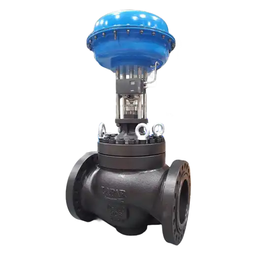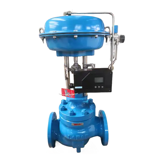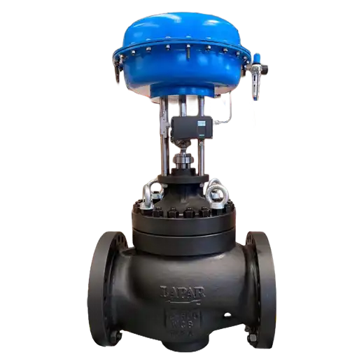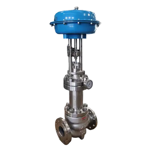
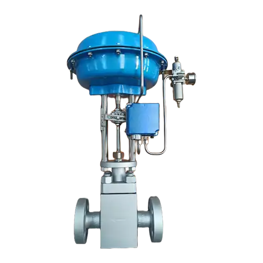
High Pressure Cage Guided Control Valve — engineered for letdown duties up to ASME Class 4500, using multi-stage and multi-path trim to hold fluid velocity, noise and cavitation inside survivable limits in forged F22, F91 and stainless bodies, DN 15 to DN 300.
How High-Pressure Valves Actually Fail
High-pressure control valves rarely fail where the pressure rating suggests they should. The body holds. The bonnet holds. What fails first is the trim, and it fails in a recognisable sequence: the leading edge of the plug and the downstream corners of the cage windows begin to erode, the polished seat surface develops wire-drawn grooves, leakage rises through Class IV to something unmeasurable, and the noise that was a steady hiss becomes a crackle and then a rattle that the operator can feel through the floor. Six weeks into service, a valve specified by pressure class alone is a leaking, vibrating, expensive problem. The reason is that at high differential pressure the governing constraint is not whether the body can contain the fluid — it is how much kinetic energy the trim releases into the fluid, and where.
That distinction reshapes the entire specification. Taking a standard valve and rating it Class 2500 changes the wall thickness, the bolting and the flange faces, and does nothing whatever about velocity at the vena contracta. A proper high-pressure design starts from the energy: the trim divides the total differential into a series of controlled steps so that pressure at no point falls below the fluid's vapour pressure, and so that outlet velocity stays under the erosion limit for the selected materials. Multi-stage drilled cages, tortuous-path labyrinth stacks and multi-hole flow splitters each do this differently, and the correct choice depends on whether the service is cavitating liquid, flashing liquid, clean gas or dirty steam. Bodies are forged rather than cast where the pressure class and temperature demand it, because forging gives the directional grain strength and the soundness that high-energy service requires.
The secondary consequences of high pressure follow from the same physics. Thrust on the plug rises with differential, so either the trim must be pressure-balanced or the actuator grows until it is uneconomical and slow. Stem packing is driven harder against the stem by line pressure, so die-formed graphite with live loading and a controlled stem finish become requirements rather than options. Flange faces move from raised face to ring type joint above certain pressure-temperature combinations, because a spiral-wound gasket cannot be trusted to seal there. Bonnet design moves toward pressure-seal constructions where the seal is loaded by the process itself. None of these are accessory decisions — each one is a direct consequence of operating pressure and each one has to be resolved before the valve can be built.
Angle-pattern bodies deserve separate mention, because they are frequently the right answer and frequently omitted from consideration. Where the letdown involves flashing, entrained solids or very high outlet velocity, an angle body directs the flow straight down and out of the valve rather than turning it against the body wall, which moves the wear from an irreplaceable casting onto the downstream spool piece and lets the outlet be sized for velocity rather than for connection convenience. We specify body pattern, stage count, trim metallurgy, balance arrangement, bonnet type, gasket class and actuator sizing together, from your process data sheet, using velocity, noise and cavitation calculations rather than a Cv lookup — and where a standard Class 600 valve would serve your duty perfectly well, we will say so instead of selling you a Class 2500 body you do not need.
Key Features
- Multi-Stage and Multi-Path Trim Sized by Energy, Not by Cv
- Multi-stage drilled-hole cages divide the total differential into a calculated number of steps so that interstage pressure never drops below the fluid's vapour pressure.
- Tortuous-path labyrinth trim stacks dissipate energy through direction changes rather than restriction, for the highest-energy liquid letdown duties.
- Multi-hole cages split the flow into numerous small jets, dispersing acoustic energy and limiting the peak velocity in any single passage.
- Stage count, hole diameter and passage geometry are calculated per ISA S75.17 / IEC 60534-8-3 and IEC 60534-8-4 for your specific pressure, temperature and medium.
- Pressure Classes to ASME Class 4500
- Class 900, 1500, 2500 and 4500 per ASME B16.34, with DIN PN 160, PN 250 and PN 400 equivalents.
- Ring type joint (RTJ) flange faces per ASME B16.5 / B16.20 at the pressure-temperature combinations where spiral-wound gaskets are no longer reliable.
- Bolted bonnets with die-formed graphite or spiral-wound gaskets, and pressure-seal bonnet constructions where the seal is loaded by process pressure itself.
- Forged Bodies for High-Energy Service
- A182 F22 and F91 / F911 chrome-moly forgings for high-temperature steam and hydrogen service, where creep strength governs.
- A182 F316 / F316H, F51 and F55 stainless and duplex forgings for corrosion-resistant high-pressure duty.
- A105 carbon steel and 4130 / 4140 alloy steel forgings for general high-pressure hydrocarbon service.
- Cast WC6, WC9, C12A and CF8M bodies offered where the size and pressure combination makes forging unnecessary.
- Trim Metallurgy Selected Against Erosion and Galling
- 17-4PH H900 / H1025 and 410 for general duty; Inconel 718 and X-750 for high-temperature strength retention.
- Solid Stellite 6 plugs, seats and cages where erosion resistance matters more than cost.
- Tungsten carbide and ceramic components available for the most severe erosive and flashing services.
- Nitrided and hard-chromed stem surfaces for packing life and galling resistance under high seating load.
- Pressure-Balanced Trim Keeps Actuator Size Practical
- Balance port and balance seal ring cancel most plug thrust at very high differential pressure, so a standard diaphragm or piston actuator remains adequate.
- Unbalanced solid trim offered for small bores, the tightest leakage classes, and services where solids would plug a balance port.
- High-tensile stems in 17-4PH or Inconel X-750 sized against the full thrust plus the safety factor required for the specified fail action.
- Angle-Pattern Bodies for Flashing and Erosive Letdown
- Flow directed axially downward and out of the body rather than turned against the body wall.
- Moves erosion onto the replaceable downstream spool piece instead of onto an irreplaceable casting.
- Allows the outlet connection to be sized for velocity control rather than for piping convenience.
- Stem Sealing Designed for High-Pressure Differential
- Die-formed graphite packing sets with live loading, maintaining seal load as the packing relaxes under thermal cycling.
- Controlled stem surface finish and hardness to prevent packing wear and leakage paths.
- Low-emission configurations per ISO 15848-1 and TA-Luft; bellows-sealed bonnets with safety packing backup for toxic and fugitive-emission-sensitive media.
- Verified Performance and Full Traceability
- Hydrostatic shell and seat testing per API 598 and IEC 60534-1; seat leakage to ANSI/FCI 70-2.
- Noise prediction to IEC 60534-8-3 (aerodynamic) and IEC 60534-8-4 (hydrodynamic), supplied with the valve.
- Material traceability, PMI verification, NACE MR0175 / ISO 15156 compliance for sour service, and PED 2014/68/EU and ATEX conformity.
Typical Applications
High-Pressure Steam Letdown
Reduction from supercritical and ultra-supercritical boiler pressures, HRSG outlets and high-pressure steam mains to process and heating headers. Multi-stage trim limits the aerodynamic noise that a single-restriction letdown would generate, and F22 or F91 bodies retain strength at the header temperature.
Boiler Feedwater and Start-Up Recirculation
Feedwater control, minimum-flow recirculation and start-up letdown against full pump discharge pressure. Balanced trim allows responsive actuation at differential pressures that would otherwise demand an oversized actuator, and hardened trim survives the continuous throttling duty.
Hydrocracker and Hydrotreater Letdown
Reactor effluent, hot and cold separator level control and high-pressure separator letdown in hydrogen-rich service at elevated temperature and pressure. F22 / F91 bodies and NACE-compliant trim address both creep strength and hydrogen attack and sulfide stress cracking.
Oil and Gas Production Choke and Test Separator Duty
Wellhead letdown, production choke replacement, test separator pressure control and manifold reduction where sand and scale may be entrained. Angle-pattern bodies with erosion-resistant trim direct abrasive flow away from the pressure-containing wall.
Natural Gas Pressure Reduction and Distribution
Transmission-to-distribution letdown, fuel gas header control, compressor recycle and vent and blowdown systems. Multi-hole trim controls aerodynamic noise at the high pressure ratios that generate the most acoustic energy.
Amine, Glycol and Gas Treating Letdown
Rich amine letdown from absorber to regenerator, glycol regeneration pressure reduction and flash drum inlet control. Differential pressure across the rich amine letdown causes flashing and erosion-corrosion; staged trim and duplex or 316 metallurgy are specified accordingly.
Petrochemical Reactor Feed and Product Control
High-pressure reactor charging, ethylene and propylene process letdown, polymerisation feed control and product transfer between pressure stages. Tight shutoff capability and stable modulation across wide turndown are both required at these pressures.
Power Generation Auxiliary and Attemperator Circuits
Desuperheating spray water injection, auxiliary steam reduction, sootblower supply control and turbine bypass systems in thermal and combined-cycle plants. These positions see continuous high-cycle operation against high differential and are unforgiving of trim erosion.
Cryogenic and LNG High-Pressure Letdown
Liquefied natural gas, nitrogen, oxygen and ethylene pressure reduction at temperatures down to -196 °C. Austenitic forged bodies, extended bonnets to keep the packing box clear of the cold zone, and degreased oxygen-clean construction where the medium requires it.
Water, Effluent and Desalination High-Pressure Duty
Reverse osmosis energy recovery and brine letdown, high-pressure pump recirculation, and industrial effluent pressure reduction. Cavitating liquid letdown is the classic multi-stage trim application, where a single-restriction valve destroys itself within weeks.
What links every one of these duties is that the pressure differential, not the pressure rating, drives the design. A valve at Class 2500 handling a modest drop across it is an ordinary valve in an expensive body; a valve at Class 600 letting down from saturated conditions to atmosphere may be one of the most severe applications in the plant. The specification therefore has to be resolved from the actual energy released across the trim — upstream and downstream pressure, temperature, medium and its vapour pressure, flow range, allowable noise, allowable outlet velocity and any entrained solids — and then worked backwards to the stage count, the trim geometry, the materials, the body pattern and the actuator. Sizing by Cv alone will produce a valve that passes the flow test and fails in service. We run the velocity, noise and cavitation calculations before we quote, supply the predicted noise figure with the valve, and will recommend a lower pressure class or a different valve family where your duty does not call for this one.
Technical Specifications
Size, Pressure and Temperature
Valve Size: DN 15 - DN 300 (NPS 1/2 - NPS 12); larger sizes on engineered request
Pressure Class: ASME Class 900, Class 1500, Class 2500, Class 4500; DIN PN 160, PN 250, PN 320, PN 400
Operating Temperature: -196 °C to +593 °C (-320 °F to +1100 °F), limited by body material, trim and bonnet selection
Maximum Differential Pressure: to full body rating; trim stage count determined by allowable outlet velocity, noise limit and cavitation index
Valve Style: Straight (globe) pattern, Angle pattern, Y-pattern
Trim Design and Flow Control
Trim Type: Cage guided single seat, pressure-balanced and unbalanced; multi-stage anti-cavitation trim
Cage Configuration: Standard window, Multi-hole, Drilled-hole multi-stage, Tortuous-path labyrinth stack, Characterized contoured plug, Micro-flow / low-Cv trim
Flow Characteristic: Linear, Equal Percentage, Quick Opening, Custom characterized profile
Seat Leakage: Class IV, Class V per ANSI/FCI 70-2; Class VI with soft seat at limited temperature
Seat Type: Metal-to-metal lapped, Stellite hard-faced, Solid Stellite, Soft seat PCTFE / PEEK / graphite at reduced temperature
Turndown Capability: up to 50:1 with characterized trim and positioner; higher on micro-flow trim
Body and Trim Materials
Forged Body Materials: A182 F22 Cl.3, F91 / F911, F11, F5, F9, F316 / F316H, F321, F347, F51, F55, A105, 4130 / 4140
Cast Body Materials: WC6, WC9, C5, C12, C12A, LCC, CF8, CF8M, CF3M, A890 4A / 5A duplex and super-duplex
Trim Materials: 316 / 316L, 410, 420, 17-4PH H900 / H1025, Alloy 6 (Stellite) hard-faced, solid Stellite 6, Hastelloy C276, Inconel 625, Inconel 718, Inconel X-750, Tungsten carbide, Ceramic
Stem Material: 17-4PH, Inconel X-750, 410, 316 — nitrided or hard-chromed for packing life
Balance Seal Material: Graphite, PTFE, FKM, Piston ring — selection sets the balanced trim temperature ceiling
Bonnet, Gasket and Stem Sealing
Bonnet Type: Bolted with die-formed graphite gasket, Spiral-wound gasket, Pressure-seal bonnet, Extended (high temperature), Cryogenic, Finned, Bellows-sealed with safety packing backup
Stem Seal: Live-loaded die-formed graphite, PTFE V-ring, High-pressure packing set with lantern ring
Emission Control: Low-emission systems per ISO 15848-1 and TA-Luft
End Connections: Flanged (ASME B16.5 / B16.47, DIN EN 1092-1), Ring Type Joint (RTJ) per ASME B16.20, Butt-weld, Socket-weld, Hubbed high-pressure connection
Face-to-Face: IEC 60534-3-2 / ISA 75.01, EN 558
Actuation and Instrumentation
Actuator Type: Pneumatic diaphragm (high-spring-range), Pneumatic piston, Hydraulic, Electro-Hydraulic, Electric, Manual handwheel with gear reduction
Fail Action: Fail Open, Fail Close, Fail Last Position
Topworks Interface: ISO 5211 / standard yoke mounting
Accessories: Smart positioner (4-20 mA / HART / Foundation Fieldbus / Profibus), Electro-pneumatic positioner, Limit switch box, Solenoid valve, Air filter regulator, Volume booster, Air lock relay, Position transmitter, Manual override, Locking device, Hydraulic power unit
Standards, Testing and Certification
Design Standards: ASME B16.34, IEC 60534, EN 12516, ASME B16.5 / B16.20 / B16.47 for connections
Testing Standards: API 598 shell and seat, ANSI/FCI 70-2 seat leakage, IEC 60534-1, ISO 5208
Noise Calculation: IEC 60534-8-3 (aerodynamic), IEC 60534-8-4 (hydrodynamic), ISA S75.17 — predicted noise figure supplied with the valve
Certifications: CE / PED 2014/68/EU, ATEX, ISO 9001, NACE MR0175 / ISO 15156 for sour service, SIL-capable, TA-Luft, Fire-safe design on request, Material traceability with PMI verification
Service Conditions and Media
Media: Supercritical and superheated steam, Boiler feedwater, Condensate, Hydrogen-rich hydrocarbon streams, Natural gas, Process gas, Crude oil and produced water, Rich amine and glycol, LNG and cryogenic fluids, High-pressure water, Brine and RO reject
Critical Service: Very high differential pressure, Cavitation, Flashing, Noise abatement, Erosive and sand-laden, Creep-limited high temperature, Hydrogen attack, Sour service, Cryogenic, Continuous high-cycle throttling
Industries: Power Generation, Oil and Gas Upstream and Midstream, Refining, Petrochemical, Fertiliser and Ammonia, Chemical Processing, LNG and Industrial Gases, Desalination and Water Treatment, Metals and Mining
Governing Criteria: High-pressure valve sizing is limited by trim outlet velocity, predicted noise level and cavitation index — not by Cv or by the body pressure rating. A valve that passes a Cv check may still destroy its trim in weeks if the energy released across a single restriction exceeds the material's erosion resistance. Stage count, hole geometry and body pattern must therefore be calculated from the actual pressure, temperature, medium and vapour pressure before the valve is specified, and the governing limit will normally be one of velocity, noise or cavitation rather than capacity.
Other Configurations: Consult our engineering team for sizes above DN 300, pressures above Class 4500, exotic alloys, oxygen-clean and degreased construction, tungsten carbide or ceramic trim, multi-stage trim retrofit into existing bodies, or complete actuated assemblies with hydraulic power units and control panels.
Frequently Asked Questions
At what point does a control valve become a "high pressure" valve?
There is no single pressure at which the design changes — what changes is the relationship between pressure and temperature. Class 900 and above typically require attention to forged rather than cast bodies, ring type joint rather than raised-face flanges, pressure-seal or heavily bolted bonnets, high-tensile stems and hardened trim. More importantly, the differential pressure across the trim usually rises with the rating, which is what makes velocity, noise and cavitation the governing design constraints rather than body strength.
Why does a high-pressure valve need multi-stage trim instead of a standard cage?
Because a single restriction converts the entire pressure drop into fluid kinetic energy at one point. At high differential that energy produces velocities far above the erosion limit of any practical trim material, and in liquid service it drops the pressure at the vena contracta below the vapour pressure, causing cavitation that destroys the plug and cage. Multi-stage trim divides the drop into a calculated number of steps so that no single stage exceeds those limits, which is the difference between a trim that lasts years and one that lasts weeks.
Should I specify an angle-pattern body for high-pressure letdown?
Usually yes where the service involves flashing, entrained solids or very high outlet velocity. An angle body directs flow axially downward and out of the valve rather than turning it against the body wall, so erosion occurs in the replaceable downstream spool piece instead of in the pressure-containing casting. It also lets the outlet be sized for velocity control. For clean, non-flashing liquid or gas letdown a straight-pattern body is normally adequate and more economical.
What leakage class is realistically achievable at high differential pressure?
Class V is achievable with precision-lapped hardened metal seats and is the normal specification for high-pressure letdown duty. Class VI bubble-tight closure requires a soft seat, which caps the maximum operating temperature well below what the body can withstand, so it is only appropriate where the temperature permits. Class IV is standard for general high-pressure service. Tell us the leakage class, operating temperature and differential pressure together — these constrain one another and cannot be specified independently.
How is noise predicted and limited at high pressure?
Aerodynamic noise from gas and steam letdown is calculated to IEC 60534-8-3, and hydrodynamic noise from liquid service to IEC 60534-8-4, using the actual upstream and downstream pressure, temperature, flow and medium properties. Where the predicted level exceeds your specification, the trim is revised — more stages, more and smaller holes, or a labyrinth path — and the calculation is rerun. This should be done before the valve is ordered; adding acoustic lagging or a downstream silencer afterwards treats the symptom and is almost always more expensive than specifying the correct trim.