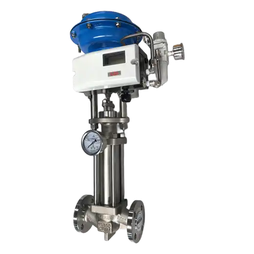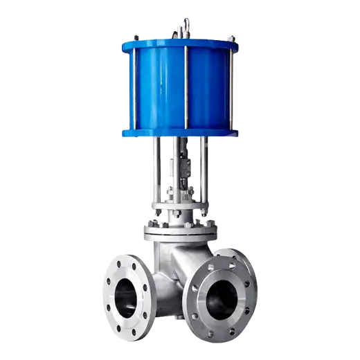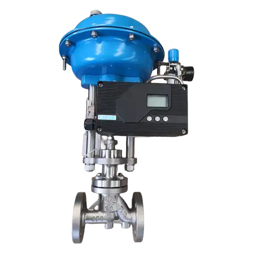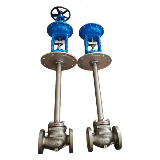
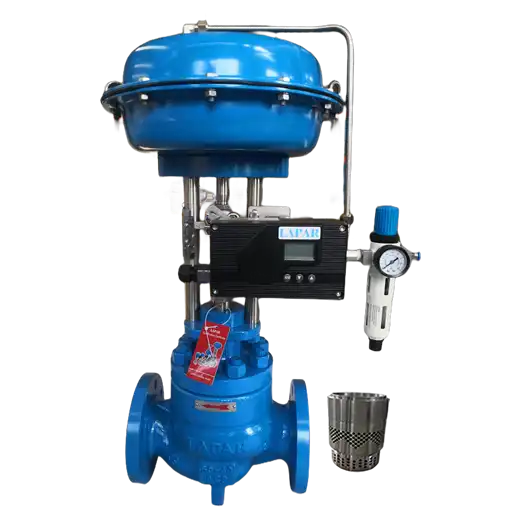
Low-noise trim control valve uses purpose-designed cage and trim geometry to break up the turbulent jet that generates aerodynamic noise in gas, steam and vapor service, reducing sound pressure level at the source rather than downstream.
Product Description
Noise from a control valve is not a nuisance to be treated after the fact — it is a symptom of how energy is being dissipated. In compressible service, the pressure drop accelerates the gas to high velocity at the restriction, and that jet converts a large fraction of the available mechanical energy into broadband acoustic energy. The sound radiates through the pipe wall, travels downstream with the flow, and where it exceeds the plant or community limit it becomes a permit issue, a personnel exposure issue under hearing conservation rules, and often a vibration problem that loosens instrumentation and small-bore connections.
The conventional remedies treat the symptom. Downstream silencers, acoustic lagging and heavy-wall pipe all reduce transmitted sound, and all of them add cost, weight, pressure drop and maintenance access problems. The more direct approach is to stop generating the noise, which is what a low-noise trim does. Rather than releasing the entire pressure drop through one large orifice that produces a single coherent high-velocity jet, the trim distributes the flow across many small passages, or stages it through successive restrictions. That shifts the generated sound energy upward in frequency, where it is attenuated far more effectively by the pipe wall and by distance, and reduces the peak levels that drive both community noise and pipe vibration.
Selecting the right attenuation trim requires predicting the noise first. Aerodynamic noise prediction follows IEC 60534-8-3, which takes the valve style, trim geometry, pressure ratio, flow and downstream piping into account, and which is the basis for stating an expected sound pressure level rather than an unverified claim. This matters because noise is fluid-dependent: gas service, steam service and flashing liquid service generate noise by different mechanisms and respond to different trim solutions. Where liquid cavitation is the dominant mechanism, the correct answer is an anti-cavitation multi-stage trim rather than a purely acoustic design. Distinguishing which mechanism is actually driving the noise is the first step, and it is the step most often skipped.
Key Features
- Noise generated less, not just attenuated more: trim geometry reduces acoustic energy at the source instead of relying solely on downstream silencers or lagging.
- Multi-hole and staged cage designs: flow is distributed across many small passages or successive restrictions, shifting generated sound to higher frequencies that the pipe wall attenuates more effectively.
- Prediction per IEC 60534-8-3: expected sound pressure level is calculated from valve style, trim, pressure ratio, flow and downstream piping rather than estimated.
- Reduced pipe vibration: lower peak acoustic energy also reduces the structure-borne vibration that damages instrumentation and small-bore connections.
- Mechanism-matched trim selection: aerodynamic noise, steam noise and cavitation-driven noise are addressed with different trim approaches, identified before selection.
- Standard body and automation: attenuation trim fits the standard body envelope, so no change to actuators, positioners or piping is required.
Typical Applications
- Steam letdown and pressure reducing stations — main and auxiliary steam where high pressure ratio generates sustained high noise levels.
- Compressor antisurge and recycle lines — high velocity gas recycling where noise and vibration are both present.
- Gas transmission, metering and regulator stations — where community and fence-line noise limits apply.
- Vapor recovery and flare header control — large pressure ratios with variable composition and flow.
- Vent, purge and blowdown systems — intermittent high-ratio releases where peak level, not average level, drives the complaint.
Noise problems are usually quoted as a decibel number, but that number is the output of a calculation, not a specification you can order against. What determines success is the mechanism: aerodynamic jet noise, steam noise, or cavitation — and each has a different correct answer. We predict the expected sound pressure level per IEC 60534-8-3 using your actual pressure ratio, flow and downstream piping, identify which mechanism dominates, and select the trim that addresses that mechanism. Where a silencer is still required, we will say so; where the right trim removes it, that is cost, weight and maintenance access saved.
Technical Specifications
| Valve Size | NPS 1 – NPS 16 / DN 25 – DN 400 |
|---|---|
| Pressure Class | ASME Class 150 to 900; DIN PN16, PN25, PN40, PN63, PN100 |
| Operating Temperature | -29 to +595 °C / -20 to +1100 °F |
| Process Connection | Flanged, Butt Weld, Socket Weld, Custom |
| Body Style | Straight (Globe), Angle |
| Bonnet | Standard, High Temperature (Finned / Extension), Cryogenic |
| Stem Seal | Adjustable Packing (bellows seal available) |
| Trim | Multi-hole cage, stacked plate or staged attenuation cage; characterized for linear or equal-percentage control |
| Noise Prediction | Aerodynamic noise calculated per IEC 60534-8-3 |
| Seat Leakage | Class IV, Class V per ANSI/FCI 70-2 |
| Flow Characteristics | Linear, Equal Percentage, Quick Open, Custom |
| Critical Service | Noise Abatement, Aerodynamic Noise, Steam Service, High Pressure Ratio, Vibration Control |
| Actuator | Pneumatic Diaphragm, Piston, Electric, Hydraulic |
| Accessories | Positioner, Position Transmitter, Limit Switch, Solenoid Valve, Volume Booster, Air Filter Regulator |
| Certifications | ANSI/ISA, ASME, NACE, PED, ATEX, SIL capable |
| Media | Gases, Steam, Vapors |
| Industries | Power, Oil & Gas, Refining, Chemical & Petrochemical, Industrial Gases, Metals & Mining |
Frequently Asked Questions
What is the difference between low-noise trim and anti-cavitation trim?
They address different mechanisms. Low-noise trim targets aerodynamic noise in gas, steam and vapor service, where a high velocity jet converts pressure energy into sound. Anti-cavitation trim targets cavitation in liquid service, where vapor bubbles form and collapse and damage metal. Where cavitation is the dominant noise source, anti-cavitation trim is the correct answer.
Can this valve eliminate the need for a downstream silencer?
Often it substantially reduces the requirement, and in some cases removes it. Whether it does depends on the predicted level, the allowable limit and the downstream piping, which is why prediction per IEC 60534-8-3 comes before selection rather than after.
How is the noise level determined?
Aerodynamic noise is predicted using IEC 60534-8-3, which accounts for valve style, trim geometry, pressure ratio, flow and downstream pipe schedule and diameter. That gives an expected sound pressure level instead of a qualitative claim.
Does the trim reduce vibration as well as noise?
Generally yes. Both are driven by the same turbulent energy, so reducing peak acoustic generation also reduces the structure-borne vibration that damages instrumentation, small-bore connections and supports.
Does low-noise trim reduce flow capacity?
Attenuation geometry changes the flow path, so capacity must be recalculated rather than carried over from a standard trim. The valve should be sized with the attenuation trim's own flow coefficient, not the standard trim value.
Resources
Data Sheets:
Manuals: IOM
Product Photos: