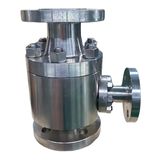
Automatic recirculation valve protects a centrifugal pump from low-flow damage by sensing the main flow and opening a staged recirculation bypass automatically when flow falls below the pump's minimum continuous flow — with no instrument air, power or control loop.
Product Description
A centrifugal pump converts a significant portion of its input energy into heat, and it relies on the process flow to carry that heat away. When flow falls below the manufacturer's minimum continuous stable flow, the pump begins to heat its own fluid: temperature rises, vapour forms, suction and discharge pressures become unstable, and the resulting damage accumulates as seal failure, impeller erosion, bearing damage and shaft deflection. This is why minimum flow protection exists, and why it is not optional on pumps that can be throttled, blocked in, or run against a closed discharge.
The conventional protection is a control loop: a flowmeter, a controller, an actuated valve on a bypass line, and the air and wiring to support them. That works, and it is also four devices, a loop to tune, a set of failure modes, and a bypass line with its own pressure reduction — typically several stages of restriction to drop pump discharge pressure back to suction or to a receiver. An automatic recirculation valve performs the same function in a single body. It senses main flow through the position of an internal flow-sensing element, and as main flow falls, it progressively opens a bypass port that returns fluid through an integrated multi-stage pressure reducing section. As main flow rises, the bypass closes. Nothing external drives it.
Three details determine whether the installation performs. The bypass pressure reduction must be staged, because the bypass sees the full pump differential — dissipating that across a single restriction would destroy the bypass trim and generate severe noise. The sensing element must be matched to the actual minimum flow requirement, which comes from the pump manufacturer's curve, not from a rule of thumb. And the valve must be installed where the sensing element sees true main flow, with the bypass returned to a point that can accept the recirculated fluid at the reduced pressure — typically the suction vessel or a receiver, never directly into a pump suction line that cannot absorb the heat.
Key Features
- Automatic minimum flow protection: senses main flow and opens the bypass as flow falls, with no operator action or control signal.
- Integrated staged pressure reduction: the bypass is built to absorb the full pump differential across multiple stages rather than a single restriction.
- No external power or instrumentation: no flowmeter, controller, instrument air, wiring or loop tuning required.
- Single-body replacement for a loop: combines flow sensing, bypass throttling and pressure reduction in one valve, removing the separate bypass valve and its actuator.
- Check function integrated: the main flow path includes a non-return element, preventing reverse flow through the pump.
- Continuous modulation: the bypass modulates with flow rather than switching, so recirculation starts before the minimum flow threshold is reached.
Typical Applications
- Boiler feedwater pump protection — the classic duty, where pumps run against widely varying demand and high differential.
- Process and charge pump minimum flow control — protecting pumps that can be throttled or blocked in during operation.
- Cooling water and circulating water pumps — maintaining minimum flow during low-demand periods.
- Condensate and heater drain pump protection — services where flow varies with load and suction conditions are marginal.
- High differential process pumps — where the bypass pressure reduction requirement is severe and must be staged.
Pump protection is one of the few places where a single component genuinely replaces a control loop, and the replacement is worth making because it removes failure modes rather than adding them — there is no flowmeter to foul, no loop to detune, and no air supply to lose at the moment protection is needed. The selection is not guesswork: it starts from the pump manufacturer's minimum continuous stable flow, which is the number the sensing element and bypass capacity are set against. We size the bypass for your actual differential and required recirculation rate, confirm the staging against the pressure drop, and specify the return point so the recirculated fluid is absorbed where it can be.
Technical Specifications
| Valve Size | NPS 1 – NPS 12 / DN 25 – DN 300 (main line) |
|---|---|
| Pressure Class | ASME Class 150 to 2500; DIN PN16, PN40, PN63, PN100, PN250 |
| Operating Temperature | -29 to +400 °C / -20 to +750 °F |
| Control Function | Automatic minimum flow recirculation; modulating bypass with rising bypass flow as main flow falls |
| Bypass Pressure Reduction | Integrated multi-stage reducing section, staged for full pump differential |
| Flow Sensing | Internal flow-sensing element matched to pump minimum continuous flow |
| Power Requirement | None — self-acting on main flow |
| Process Connection | Flanged, Butt Weld, Socket Weld, Custom |
| Body Style | Straight, Angle |
| Integrated Functions | Flow sensing, non-return check element, staged bypass pressure reduction |
| Critical Service | Pump Protection, Minimum Flow, High Differential Bypass, Boiler Feedwater, No Air Supply |
| Body Materials | Carbon Steel, Stainless Steel, Alloy Steel |
| Certifications | ASME, PED, ATEX (no electrical components) |
| Media | Water, Boiler Feedwater, Condensate, Process Liquids, Hydrocarbons |
| Industries | Power, Refining, Chemical & Petrochemical, Water & Wastewater, Oil & Gas, Pulp & Paper |
Frequently Asked Questions
Why does a centrifugal pump need minimum flow protection?
Because the pump relies on process flow to remove the heat it generates. Below the manufacturer's minimum continuous stable flow, the fluid heats, vapour forms, pressures become unstable, and damage accumulates as seal failure, impeller erosion, bearing damage and shaft deflection.
How does this differ from a control loop with a flowmeter?
It performs the same function in one self-acting body. There is no flowmeter to foul, no controller, no actuator, no instrument air, and no loop to tune — which removes failure modes rather than adding them.
Why must the bypass pressure reduction be staged?
Because the bypass sees the full pump differential. Dissipating that across a single restriction would destroy the bypass trim and generate severe noise, so the reduction is divided across multiple stages.
What determines the bypass setpoint?
The pump manufacturer's minimum continuous stable flow from the pump curve, not a rule of thumb. The sensing element and bypass capacity are set against that number.
Where should the recirculated flow return?
To a point that can absorb it at the reduced pressure — typically the suction vessel or a receiver. It should not be returned directly into a pump suction line that cannot dissipate the recirculated heat.