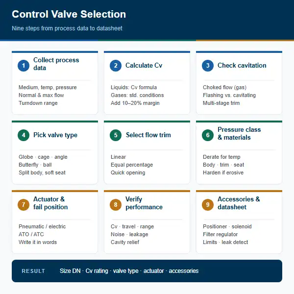
Two things are worth stating up front, because most bad selections trace back to skipping them. First, the valve is sized by its flow coefficient, then matched to a bore size — not the other way round. Second, every step after Step 1 is constrained by the data collected in Step 1, so an approximate figure in the datasheet request propagates all the way to a valve that cannot control the process.
Step 1 — Collect process data
Nothing downstream is reliable if this step is approximate. Capture the following, and mark clearly which values are normal, maximum and minimum operating cases.
| Parameter | Why it matters | Typical source |
|---|---|---|
| Fluid composition and phase | Decides material, seal and cavitation behaviour; a fluid that is safe as liquid may not be safe as vapour | Process datasheet, MSDS |
| Flow rate: min, normal, max | Sets the Cv envelope; max alone is not enough | Mass and energy balance |
| Upstream and downstream pressure (P1, P2) | Defines available pressure drop; absolute pressure is required, not gauge | Line hydraulics |
| Design and operating temperature | Selects material grade, seat material and bonnet class; also enters the Cv temperature correction | Process conditions |
| Density, specific gravity, viscosity | Feeds Reynolds number for flow regime and corrects liquid Cv | Property data at operating temperature |
| Vapour pressure at operating temperature | The single most important number for cavitation and flashing decisions | Property data or steam table |
| Pipe size and schedule | Sets the line bore, and therefore the maximum practical velocity | Piping isometrics |
| Design requirements: shutoff class, noise limit, service type | Drives seat material and trim selection | Project specification |
Process data sheet: the minimum set for a single valve line.
Also capture the vapour pressure at the maximum possible temperature, not only at normal temperature. A line that does not flash at 40 °C can flash at 90 °C during a start-up or a runaway, and this is a common cause of trim damage that appears months after commissioning.
Step 2 — Calculate the flow coefficient Cv or Kv
The flow coefficient expresses how much flow a fully open valve will pass at a unit pressure drop. Cv is defined as the flow in US gallons per minute that gives a 1 psi drop across the valve, with water at about 60 °F. Kv is the metric equivalent: cubic metres per hour at a 1 bar drop, with water at 15–20 °C. They are related by a constant:
Liquid sizing
For liquids in US units, the standard sizing relationship is:
| Symbol | Meaning |
|---|---|
| Q | Liquid flow rate in US gpm |
| N | Number of independent flow paths through the trim (two for an angle valve, one for a globe) |
| P1 − P2 | Available pressure drop across the valve, in psi |
| Ft | Temperature correction factor for the fluid viscosity |
| Fl | Liquid recovery factor, accounting for pressure recovery downstream of the seat |
| Fp | Piping geometry factor, accounting for fittings and reducers in the flow path |
Symbols and their meaning. Use absolute pressure in psia.
Gas and steam sizing
Gas and steam sizing follows the same structure but includes compressibility and temperature in absolute units, and it is far more sensitive to input errors. Use the manufacturer's sizing program for these services, and use the equation below as a sanity check rather than as the primary calculation. For a gas with specific gravity S, compressibility factor Z, and flow Qg in standard cubic feet per hour at 14.7 psia and 60 °F:
Here T is absolute temperature in Rankine. For metric sizing, Kv is calculated from Q in m³/h, pressures in bar absolute, and density in kg/m³. Because these calculations are unit-sensitive, specify whether the vendor is quoting Cv, Kv, or the metric Kv-equivalent, and confirm which convention the quoted figure uses before comparing bids.
Step 3 — Check choked flow, flashing and cavitation
This step decides whether the calculated Cv is even achievable. Three distinct phenomena are routinely confused, and they lead to different remedies.
| Phenomenon | What happens | Consequence | Remedy |
|---|---|---|---|
| Choked flow (gas) | Gas velocity reaches Mach 1 at the throat; flow stops responding to downstream pressure | Installed Cv exceeds the critical value; flow stays pinned at maximum regardless of valve position | Reduce the valve or add stages; check the critical pressure ratio |
| Flashing | Vapour forms because P2 falls below the vapour pressure Pv | Cavitation is avoided downstream, but the vapour jet is still erosive and noisy | Match downstream piping to the flashing flow, minimise recovered pressure, use a multi-stage trim |
| Cavitation | Vapour bubbles form and collapse back to liquid while P2 is still above Pv | Trim pitting, vibration, and severe noise; the most damaging failure mode | Keep P2 above Pv, stage the pressure drop, use anti-cavitation trim, reduce velocity |
Distinguishing the three flow-limiting phenomena.
Choked flow criterion for gases
For a gas with specific heat ratio k, flow chokes when the downstream-to-upstream absolute pressure ratio falls below the critical value:
If the calculated operating ratio sits below this value, the valve is choked, the Cv calculation no longer predicts flow, and the trim must be reduced or the pressure raised. For steam, the equivalent check compares the pressure drop against the critical ratio for the saturation properties at the inlet condition.
Cavitation criterion for liquids
Cavitation is avoided when the pressure downstream of the throat stays above the vapour pressure with a margin that accounts for velocity and for downstream recovery. A widely used screening rule is that a single stage should not be asked to absorb more than roughly 1.3 times the difference between inlet pressure and vapour pressure before cavitation becomes likely, and that large recoveries in the downstream piping make the problem substantially worse.
When the required ΔP is large and the pressure downstream is well above Pv, the practical answer is multi-stage trim: two or more seats of decreasing area share the pressure drop, so no single stage exceeds the cavitation limit. It costs size and money, and it is the correct answer far more often than it is used.
Step 4 — Select the valve body type
Body type follows from the duty, and it is the first decision that constrains the Cv calculation, because N and Fp both depend on it.
| Type | Characteristics | Typical application |
|---|---|---|
| Single-seat globe | Highest Cv per unit size, excellent throttling, N = 1, moderate recovery | General process control, heating and cooling, pressure and level control |
| Cage / guided cage | Anti-cavitation and anti-flash options, robust trim, handles dirty service | High ΔP, cavitation-prone duty, polymer and slurry service |
| Double-seat globe | Higher capacity for a given envelope; larger closed-port area raises leakage risk | High-pressure steam, where a tight shutoff is not required |
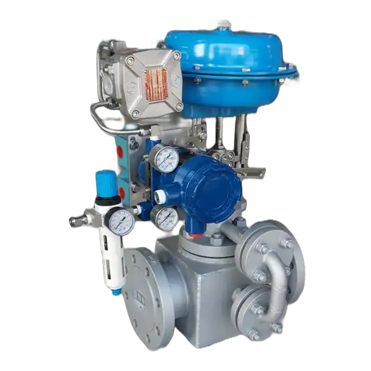
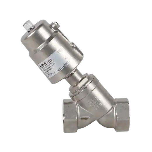
| Angle | Flow and body in one line, N = 2, high Cv per size, rotates the flow path 90° | Cavitation and flashing service, slurries, viscous or dirty fluids |
| Butterfly | Compact, low weight, large sizes, limited authority at low ΔP | Large flows at low pressure drop, HVAC, isolation with limited control |
| Multi-stage | Pressure drop split across several stages; larger body, higher cost | Very high ΔP where single-stage cavitation cannot be avoided |
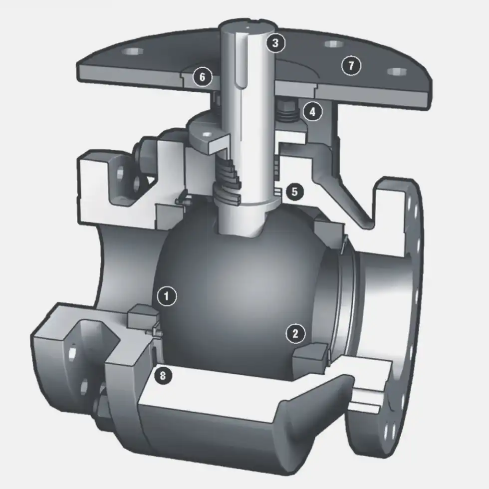
| Ball and plug | Very high capacity, very tight shutoff, limited throttling authority except characterized versions | On-off duty, high cycle, tight shutoff; characterized ball for throttling |
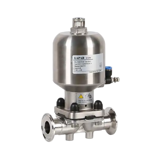
Body types and where each one belongs.
Also decide at this stage whether the valve needs a split body and removable seat. For polymer, resin, adhesive or crystallising service, a body that cannot be opened without cutting the pipe will eventually cost more than the valve saved.
Step 5 — Select the flow characteristic
The flow characteristic defines how Cv changes with stem travel. Matching it to the process gain is what makes a loop tuneable.
| Characteristic | Inherent behaviour | Match it to |
|---|---|---|
| Linear | Constant slope; 25–50% travel gives 25–50% of rated flow. Equal increments of travel give equal increments of flow | Constant process gain: heat exchangers with fixed pressure drop, simple level control, dosing |
| Equal percentage | Constant proportional change; 50% travel gives about 50% of rated Cv. Most flow change happens in the upper half of the stroke | Varying process gain, wide rangeability, most process control loops |
| Quick opening | Steep initial rise then near-linear; almost all capacity in the first quarter of travel | On-off duty, and low ΔP services needing a tight shutoff at small travel |
The three standard characteristics.
Two related sizing parameters are often bundled into the same table entry and are worth setting explicitly. Rangeability is the ratio of maximum to minimum controllable Cv, typically 30:1 to 50:1 for a conventional globe and 100:1 or more for characterized trim. Turndown is the usable ratio between minimum controllable flow and maximum rated flow. Most loops need about 30:1, and specifying more than the loop can use simply makes the valve oversized for its actual duty.
Step 6 — Specify pressure class and materials
Pressure class and material selection are a single decision, because the allowable pressure of a body is a property of the material at the design temperature, not of the class label alone.
Pressure rating
Valves are ordered to an ASME class (150, 300, 600, 900, 1500, 2500) or a PN rating (PN10 to PN100). The class is only the cold-pressure rating; every listed rating must be derated for the design metal temperature. A cast carbon steel valve rated Class 300 drops substantially in allowable pressure at 400 °C, and the derating curves are not optional reading. Confirm that the rating at the actual design temperature still exceeds the maximum operating pressure including transients and water hammer.
For liquid service, the body rating must also exceed the cavitation and system pressure at the seat. For gas service, body rating is normally based on the maximum operating pressure with a stated non-condensing or condensing basis, and the seat leakage class must be stated, since a metal seat is not gas-tight at high differential pressure.
Materials
| Component | Typical materials | Selection driver |
|---|---|---|
| Body | ASTM A216 WCB carbon steel; A351 CF8M or A316 stainless; duplex or nickel alloy for severe service | Corrosion, pressure, temperature |
| Trim | 13Cr stainless; 17-4PH; Stellite 6 hardfacing; tungsten carbide overlay for severe erosion | Cavitation, erosion, flashing |
| Seat and disc | PTFE or RPTFE for soft seats; metal seats hardened and matched for metal-to-metal | Shutoff class, temperature, media compatibility |
| Stem | 17-4PH or 316, electropolished for cyclic service | Strength, galling resistance, surface finish |
| Bonnet packing | Graphite, PTFE, or live-loaded packing for cyclic duty | Stem leakage, emission class |
Common material selections by service.
Step 7 — Choose the actuator and fail position
The actuator converts signal pressure or electrical power into stem motion, and it is the only part of the valve that interacts with the control system. The choice is driven by three questions: what drives it, what happens when the power fails, and how it is positioned.
| Actuator | Description | Failure behaviour | Use when |
|---|---|---|---|
| Pneumatic spring-return, single acting | Spring opposes the air pressure; air pressure moves the stem | Fail closed (ATO) or fail open (ATC) by spring design | Default for modulating control; fail position is spring-determined |
| Pneumatic double acting | Air pressure applied to both sides | Stays in position on loss of air | Large valves, high pressure drop, where fail position is not required |
| Electric | Motor, gear and limit switch assembly | Depends on mechanism: spring, stored energy, or battery / UPS backed drive | No instrument air available, or where air quality is poor |
| Electro-pneumatic or electro-mechanical positioner | Positioner commands the actuator from a 4–20 mA signal | As the actuator above | Hunting on direct-operated pneumatic valves; always specified for modulating duty |
Actuator types and their behaviour on loss of power.
Fail-safe coding
ATC — air to close; loss of air opens the valve (fail open)
AOI / ACI — combination override, used on dual-acting actuators where a specific position is required on failure
The fail position is a process safety decision, not a purchasing detail. The general rule is that a fail-closed valve protects people and the environment when the medium is hazardous — flammable, toxic, or a hot utility that would cause damage if it continues to flow. A fail-open valve protects the equipment and the process when stopping flow is the greater risk: freezing lines, damaging a pump or vessel by over-pressurising it, or losing cooling to a reactor that is running hot.
For valves in a safety instrumented system, specify the fail position, the SIL rating of the actuator and positioner, the proof test interval, and whether a partial stroke test is required.
Step 8 — Verify performance
Verification is where the calculated Cv is confirmed against the manufactured product, and where several independent failure modes are checked. Do not skip it because the numbers were calculated carefully.
| Check | Requirement | Reference |
|---|---|---|
| Rated Cv | Manufacturer test figure within the tolerance of the calculated requirement | IEC 60534-1 water flow test |
| Valve travel | Stroke and rated travel clearly stated; positioning resolution adequate for the loop | Manufacturer data |
| Rangeability | Minimum controllable Cv stated; confirm it covers the minimum process demand | IEC 60534-1 |
| Noise | Predicted aerodynamic and liquid noise within the stated limit | IEC 60534-8 |
| Leakage class | Seat leakage class confirmed, with the test medium stated | API 598, ISO 15848-1 for fugitive emissions |
| Cavity relief | Cavity pressure relief provided or explicitly excluded | ASME B16.34 |
| Seat orientation | Flow direction and seat orientation confirmed against the trim selected in Steps 2 to 4 | Manufacturer installation instructions |
Performance verification checklist.
Noise deserves specific attention on liquid duty with high velocity. Sound pressure scales roughly with the eighth power of velocity, so a 20% velocity increase raises noise by a factor of about 4.3. If the line is noisy, the first thing to check is whether the valve was sized for a flow it rarely sees.
Step 9 — Select accessories, finalize the specification and model number
The last step turns a selected valve into an orderable, installable item. Accessories are chosen by function: what the valve must do, what it must report, and what must be protected.
Positioning and control
- Positioner — required on any modulating pneumatic valve where the loop cannot be tuned without one, and on all split-range applications. Specify 4–20 mA or digital protocol, action on signal loss, and hazardous-area approval.
- Solenoid valve — the pilot element that switches the actuator. Specify voltage, coil type (non-explosive-proof where permitted, otherwise EEx), and function such as de-energise to trip.
- Filter regulator — required on every pneumatic actuator. Instrument air quality, typically 40 µm filtration and a regulated pressure matched to the actuator spring range, affects both reliability and positioner performance.
- Limit switches or proximity sensors — required where the control system must confirm open and closed position rather than infer it from the command signal.
- Stem leak detection — a filled bonnet or a leak-detection flange on hazardous or toxic service.
Complete specification sheet
Before issuing an enquiry, confirm that the datasheet contains every one of these. A missing field is the most common reason a quotation comes back wrong and the schedule slips.
- Tag number, service description, and line reference
- Fluid, phase, density, viscosity, and vapour pressure at maximum temperature
- Flow rate at min, normal and maximum; P1 and P2 in absolute units at each case
- Design and operating temperature, and design pressure
- Pipe size and schedule, and the flow direction requirement
- Calculated Cv or Kv, with the equations and correction factors used
- Cavitation or flashing assessment result and the chosen mitigation
- Valve type, size, body and trim material, seat material, flow characteristic
- Pressure class, end connection, and face-to-face dimensions
- Actuator type, fail position, travel, and air supply pressure and quality
- Positioner, solenoid, filter regulator, limit switches, and any special requirements
- Applicable standards, inspection and documentation requirements
Common selection mistakes
These account for a large share of avoidable problems. Each is a sequencing error rather than a knowledge gap.
- Sizing to the pipe bore. Choosing DN first and accepting whatever Cv that valve happens to have, instead of calculating Cv and then selecting a bore. This is the single most common cause of a valve that is permanently at 10% travel.
- Designing only for the maximum flow. If peak flow occurs twice a year, the valve spends the rest of its life throttling near closed. Consider split range, parallel valves, or an interchangeable trim.
- Ignoring vapour pressure at the maximum temperature. Flash and cavitation appear during start-up, not during steady operation.
- Accepting the standard trim in a cavitating service. The Cv calculation is correct, the material is correct, and the valve still fails, because the trim geometry was never reviewed against the cavitation criterion.
- Leaving the fail position to the supplier. If it is not written on the datasheet, it will be decided by catalogue default.
- Using gauge pressure in a sizing calculation. Undersizes the valve whenever P2 is well above atmospheric.
- Omitting the accessories section. A modulating valve with no positioner, no filter regulator and no solenoid is not a working control valve.
- Skipping the verification step. The manufacturer's test Cv, the noise figure and the leakage class are known data — use them.
Frequently asked questions
Standards referenced: IEC 60534-1 (valve sizing and flow coefficient testing), IEC 60534-8 (noise), ISO 5216 (face-to-face dimensions), ASME B16.34 (valve construction, cavity relief), API 598 (valve inspection and leakage testing), API 6D (pipeline valves), ISO 15848-1 (fugitive emissions), IEC 61508 (functional safety).
Engineering reference document. Values and acceptance criteria should be confirmed against the manufacturer's current sizing software, the applicable project specification, and the governing standard for the service in question.