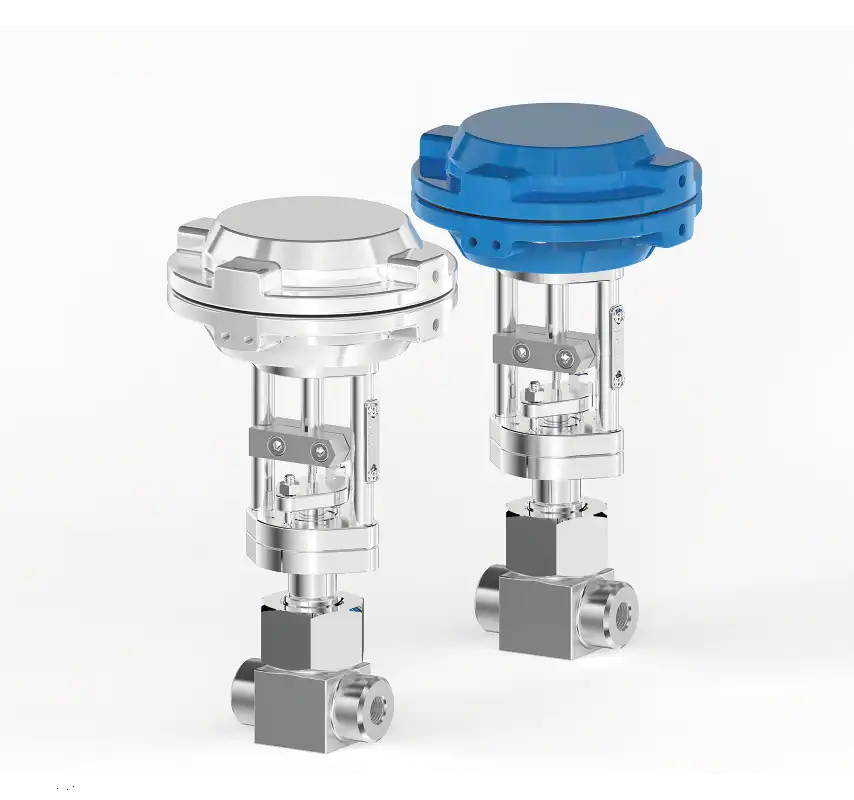
Silane (SiH4) Specialty Gas Valve Selection Guide: Technical Points for On/Off and Control Valves
Silane (SiH4) is a pyrophoric specialty gas with extremely high combustion energy and stringent purity requirements. Its handling is critical in semiconductor and photovoltaic manufacturing. Valve selection directly impacts both the safety of the facility and the yield of the production line. Based on process requirements, silane systems are generally divided into On/Off Valves (Isolation/Shut-off) and Control Valves (Flow Regulation). Below are the technical material selection criteria and core design points for both categories.
| Property | Value |
|---|---|
| Appearance and properties | Colorless gas with an odor |
| Melting point (℃) | -185.0 |
| Boiling point (℃) | -112 |
| Critical temperature (℃) | -3.5 |
| Critical pressure (MPa) | No data available |
| Relative vapor density (air = 1) | 1.2 |
| Relative density (water = 1) | 0.55 |
| Density (g/cm³) | 0.68 [at -185℃ (liquid)] |
| Heat of combustion (KJ/mol) | -1476 |
| Spontaneous combustion temperature (℃) | < -85 |
| Flash point (℃) | < -50 |
| Decomposition temperature (℃) | Greater than 400 |
| Saturated vapor pressure (kPa) | No data available |
| Octanol/water partition coefficient | No data available |
| Maximum explosion % (V/V) | 100 |
| Lower explosive limit % (V/V) | 1.37 |
| PH (indicate concentration) | Not applicable |
| Flammability | Extremely flammable |
| Solubility | Insoluble in water; soluble in benzene, carbon tetrachloride |
I. Selection Points for Silane On/Off Valves (Isolation / Shut-off)
On/off valves are primarily used for emergency shut-off, cylinder changeover isolation, or physical segregation during equipment maintenance. The core requirements are absolute zero leakage, minimal dead volume, and ultimate safety.
1. Valve Structure Selection
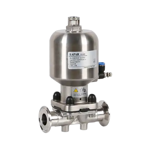
- Preferred Structure: Bellows-Sealed Diaphragm Valves. Diaphragm valves achieve open/close functions through the elastic deformation of a flexible diaphragm. Their seal-less design fundamentally eliminates the risk of external leakage at the stem dynamic seal.
- Alternative Structure: For larger bore sizes or specific high-pressure conditions, Bellows-Sealed Globe Valves can be used, provided the feature a dual-seal design combining the bellows and the stem.
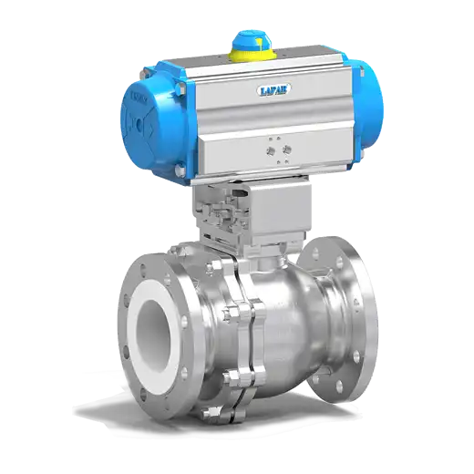
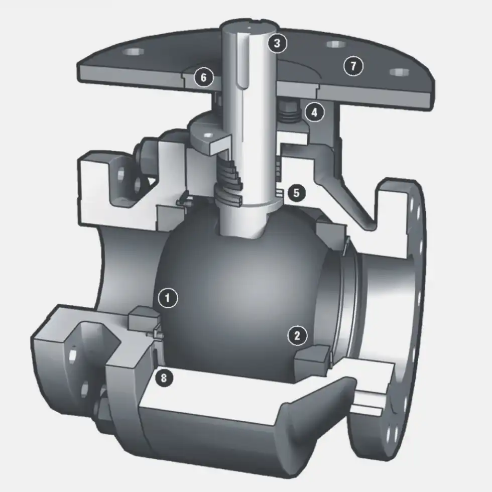
- Strictly Prohibited: Ball valves, butterfly valves, or standard gate valves are absolutely forbidden. Their internal dead cavities easily trap silane, leading to decomposition and potential explosions.
2. Materials and Surface Treatment
- Body and Internals: Must be manufactured from 316L VIM/VAR (Vacuum Induction Melt / Vacuum Arc Remelt) ultra-high purity stainless steel to minimize metallic impurity outgassing.
- Diaphragm Material: PTFE-encapsulated EPDM or FFKM (Perfluoroelastomer, e.g., Kalrez/Chemraz) is recommended. While pure PTFE offers excellent chemical resistance, its fatigue life is short; the encapsulated structure balances sealing integrity with long-term durability.
- Surface Treatment: All wetted internal surfaces must undergo Electropolishing (EP), with a surface roughness of Ra ≤ 0.25 μm, to prevent particle adhesion and moisture retention.
3. Core Design Points
- Low Dead Volume: The valve cavity must be optimized using fluid dynamics to ensure minimal residual gas volume when fully open or closed, preventing silane thermal decomposition in dead corners.
- Back-Seating Design: The stem or diaphragm assembly should feature back-seating functionality. When fully open, it forms a secondary seal barrier, preventing leakage during maintenance under pressure.
- Fire and Explosion Safety: Valves must pass relevant fire-safety tests (e.g., API 607), and external components must avoid plastics that can generate static electricity.
II. Selection Points for Silane Control Valves (Flow Regulation)
Control valves are used to precisely regulate silane flow in processes such as Chemical Vapor Deposition (CVD). Due to silane's pyrophoric nature and the extreme precision required, control valve selection is significantly more complex than that of on/off valves.

1. Valve Structure Selection
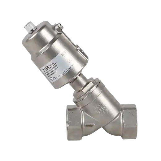
- Preferred Structure: High-Precision Pneumatic Globe Valves or Piezoelectric Valves. Pneumatic actuators offer fast response and excellent explosion-proof performance, while piezoelectric valves are ideal for ultra-low flow, high-precision micro-regulation.
- Trim Design: V-Port Plugs or Multi-Stage Labyrinth Trims are recommended. V-port plugs provide excellent equal-percentage flow characteristics and high turndown ratios (100:1 or higher). Labyrinth trims are essential for high-pressure-drop conditions to prevent excessive flow velocity that could cause localized overheating or auto-ignition.
- Flow Direction: Flow-to-Open is typically adopted. Utilizing the medium's own pressure to assist in opening reduces the actuator's thrust requirement and enhances control stability.
2. Materials and Surface Treatment
- Body and Trim: Must also utilize 316L VIM/VAR stainless steel. For areas subjected to high-velocity gas scouring (plug and seat), hard-facing treatments (e.g., Stellite alloy overlay or Titanium Nitride coating) are recommended to prevent metal wear and particle contamination over time.
- Seat Seal: PCTFE or PEEK (Polyether Ether Ketone) soft-seats are used to ensure ANSI Class VI zero-leakage shut-off even at micro-openings.
- Surface Treatment: Internal EP treatment is mandatory, followed by strict passivation to form a dense chromium oxide protective film.
3. Core Design Points
- Anti-Static and Grounding: High-velocity silane flow easily generates static charge accumulation. All metallic components of the control valve must have ultra-low contact resistance and be equipped with dedicated anti-static grounding terminals to prevent spark ignition.
- Intrinsically Safe Actuators: Pneumatic actuators must be paired with high-reliability smart positioners featuring explosion-proof certifications (e.g., Ex d IIC T4). In the event of air supply failure (Air Fail), the valve must automatically return to a safe position based on process safety requirements (typically Fail-Close).
- Particle Jamming Prevention: Silane may generate trace amounts of silicon powder in the pipeline. The clearance between the plug and seat must be specially designed to prevent micro-particles from jamming the valve or scratching the sealing surfaces.
III. General Safety and System-Level Requirements
Whether on/off or control valves, all valves in a silane system must meet the following baseline requirements:
- Helium Leak Testing: All valves must undergo rigorous Helium Mass Spectrometer Leak Testing prior to shipment. The external leak rate must be ≤ 1×10⁻⁹ atm·cc/sec He, and internal leakage must strictly comply with process specifications.
- Cleanliness Standards (Clean for Silane Service): Throughout manufacturing, assembly, testing, and packaging, valves must strictly adhere to cleanroom standards. The use of any hydrocarbon-based lubricants or cleaners is strictly prohibited.
- Integrated Safety Monitoring: The valve installation area must be equipped with high-sensitivity Silane Gas Leak Detectors (GLD) and UV/IR flame detectors. These must be hardware-interlocked with the valve's Emergency Shutdown System (ESD) for immediate isolation upon detection.
By strictly adhering to these selection guidelines, operational risks in silane piping systems can be minimized, ensuring the safety, stability, and efficiency of ultra-high purity gas processes.