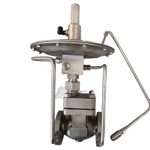
Tank nitrogen blanketing valve holds the pressure of the nitrogen pad above the liquid in a storage tank, using a self operated supply regulator to add nitrogen when the tank empties and a self operated vent regulator to release nitrogen when the tank fills, with no instrument air, electrical supply or controller.
Product Description
The blanketing arrangement uses two self operated micro-pressure control valves working as a pair. The supply valve feeds nitrogen into the tank vapor space; the vent valve releases nitrogen from it. Both are driven by the pressure of the gas they control, compared against an adjustable spring force, so neither needs air, power or a control loop. The nitrogen pad above the product is normally held at around 100 mmH2O, roughly 1 kPa, and the pair works to hold that value while the tank is pumped out and filled again.
The two valves act on opposite events. When the outlet valve opens and product is pumped out, the liquid level falls and the gas pressure drops; the supply regulator opens further and feeds nitrogen in until the pressure returns to its setpoint. When the inlet valve opens and the tank is filled, the level rises, the vapor space is compressed, and gas pressure climbs; the supply regulator closes and the vent regulator opens, releasing nitrogen until the pressure falls back to its setpoint. A tank roof breather valve is required in addition to the pair, because it is the device that protects the tank when the regulators cannot keep up, and its setpoint is set above the vent setpoint.
Setpoint coordination is where blanketing systems are usually got right or wrong. Supply setpoint, vent setpoint and breather valve setpoint are three separate values, and they must be spread apart: supply pressure Pc, vent pressure P1 and breather valve discharge pressure P2, with Pc lower than P1 and P1 lower than P2. Typical values are 1 kPa (100 mmH2O) for supply and 2 kPa (200 mmH2O) for vent, set by adjusting spring pre-compression: the main spring on the supply regulator, and the spring in the pressure controller on the vent regulator. The gaps matter. Set P1 too close to Pc and the two regulators chase each other, opening and closing in quick succession, which wastes nitrogen and wears the trim. Set P2 too close to P1 and the breather valve lifts on ordinary filling operations instead of staying reserved for genuine overpressure.
Two installation points deserve the same attention as the setpoints. Because this is micro-pressure control, the sensing line and its tapping point govern how the valve behaves. The tap belongs on the tank vapor space, the line should be short, self-draining and free of low points where condensate can collect, and the line should not be exposed to wind pressure that the valve will read as tank pressure. Capacity must be selected against the actual rates the tank sees, meaning the pump-out rate that the supply valve has to follow and the filling rate that the vent valve has to relieve. Blanketing failures are far more often a capacity or sensing problem than a setpoint problem.
Key Features
- No external energy: both regulators are driven by the gas pressure they control, so no instrument air, no wiring, no positioner and no controller.
- Supply and vent supplied as a coordinated pair: nitrogen make-up and nitrogen relief matched so the setpoints can be spread apart and the system does not cycle.
- Pressure balanced trim: the plug is balanced, which holds sensitivity and stability even though the controlled pressures are only a few hundred mmH2O.
- Low noise and maintenance free: low travel speeds and balanced trim keep operating noise down, and there are no power components to service.
- Standard modular design: flow is set through the throttle valve against the standard diagram, which makes commissioning and later adjustment straightforward.
- Combinable components: different modules can be combined to extend the arrangement to several control functions on the same tank or tank group.
Typical Applications
- Storage tank nitrogen blanketing: holding the nitrogen pad on fixed roof tanks as level changes.
- Product protection: excluding air and moisture from refined oil, solvents, chemical intermediates, edible oils and pharmaceutical products to limit oxidation and contamination.
- Emission control: keeping vapor space under an inert pad to reduce product vapor losses and vented emissions.
- Tank farms and loading terminals: blanketing multiple tanks from a common nitrogen header, with a supply regulator and a vent regulator on each tank.
- Industries served: chemical, petroleum, pharmaceutical, food, power generation, metallurgy and light industry.
Sizing a blanketing system is a capacity question before it is a product question. We ask for the tank volume, the maximum pump-out and filling rates, and the required pad pressure, then match the supply and vent regulators and the setpoint spread to those numbers. Where the tank has an existing breather valve, its setpoint has to be coordinated with the vent setpoint rather than selected independently.
Technical Specifications
| Function | Nitrogen supply (make-up) control and nitrogen vent (relief) control on a tank blanket |
|---|---|
| Valve Type | Self operated micro-pressure control valve, supply type and vent type |
| Typical Blanket Pressure | Approx. 100 mmH2O |
| Supply Setpoint, Typical | 1 kPa (100 mmH2O); set by adjusting main spring pre-compression |
| Vent Setpoint, Typical | 2 kPa (200 mmH2O); set by adjusting spring pre-compression in the pressure controller |
| Setpoint Coordination | Supply Pc, vent P1 and breather valve discharge P2, set as Pc < P1 < P2 with gaps wide enough to prevent frequent cycling |
| Control Action | Proportional, energized by the controlled gas pressure |
| Power Requirement | None, self operated |
| Pressure Balance | Pressure balanced plug |
| Flow Adjustment | Throttle valve set against the standard diagram |
| Associated Equipment | Tank roof breather valve required, set above the vent setpoint |
| Media | Nitrogen; other non-corrosive gases |
| Industries | Chemical, Petroleum, Pharmaceutical, Food, Power Generation, Metallurgy, Light Industry |
Frequently Asked Questions
What does a nitrogen blanketing valve actually do?
It keeps a nitrogen pad above the liquid in a storage tank at a low, roughly constant pressure. When the tank empties and the gas pressure falls, the supply regulator adds nitrogen. When the tank fills and the gas pressure rises, the vent regulator releases nitrogen. The point is to keep air and moisture away from the product and to cut vapor losses.
Why are there two valves instead of one?
Because the tank sees two opposite events. Pumping out creates a nitrogen demand, which one regulator can only supply. Filling compresses the vapor space and creates a nitrogen surplus, which the same regulator cannot relieve without reversing its action. A supply valve and a vent valve handle the two cases separately, and their setpoints are spread apart so they do not fight each other.
How are the setpoints adjusted?
Both are spring adjustments. The supply setpoint is set by changing the pre-compression of the main spring on the supply regulator. The vent setpoint is set by adjusting the spring in the pressure controller of the vent regulator. Typical values are 1 kPa and 2 kPa respectively.
Does it need instrument air or electricity?
No. Each regulator is driven by the pressure of the gas it controls, compared against its spring force. That is the main reason blanketing systems are built this way: a tank farm has no instrument air at the tank roof, and running one there costs more than the valve.
Why does my blanketing system open and close constantly?
Usually one of two causes. The vent setpoint is too close to the supply setpoint, so the two regulators chase each other, and the fix is to widen the gap. Or the sensing line is wrong: a long run, a line with a low point where condensate collects, or a tapping point exposed to wind will each feed the regulator a pressure that is not the tank pressure.
Resources
Data Sheets:
Manuals: IOM
Product Photos: