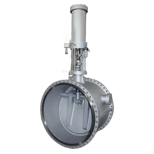
The spring assisted close extraction check valve is a fast-closing non-return valve installed on a steam turbine extraction line, built to shut off within the first second of a turbine trip so that reversing steam and condensate cannot run back into the machine.
Product Description
The duty is set by what happens when a turbine trips or rejects load. Stage pressure inside the machine collapses, while the heater, the deaerator or the process header connected to the extraction line still holds pressure. The gradient reverses and everything in that line begins moving backward toward the rotor. The damage takes two forms: reversing steam drives the rotor in a direction and at a loading it was not designed for, and any water in the line, whether heater drainback, leaking heater tubes or condensate pooled at a low point, gets carried into the casing. Water entering a running turbine erodes blades, bows rotors and destroys thrust bearings. This valve exists because capturing that event in its first second is the difference between a trip and a machine rebuild.
The main valve is a tilting-plate disc with a large eccentricity, not a swing check. That geometry gives the disc a self-closing bias: once forward flow drops away, the plate returns toward its seat under its own weight and under any reverse flow, without needing anything external to make it happen. Sealing is triple-eccentric metal: a metal sealing ring on the plate presses into the conical body seat on closure, producing true circular contact rather than line or point contact. The disc runs on slide bearings, so there is no hinge pin in the flow path to wear, seize or collect debris during the long periods the valve stands open. Metal seating is a requirement here rather than a choice: soft seats do not survive superheated steam temperature or the combination of temperature cycling and any solids carried through an extraction line.
Two construction details do the work of making that closure repeatable rather than just fast. The seating is triple eccentric in both seat and disc, and the disc is set on a large inclined seat angle so the travel between open and closed is short, and less travel is less time. The eccentric geometry lets the sealing faces meet with little friction instead of rubbing as they close. The disc runs on strong, low-friction bearings, and there is no hinge pin gland in the assembly: a hinge pin in this duty is a part that seizes on scale, wears on every cycle and sits where nothing can reach it during the months the valve stands open. The sealing face is hardened, because closure here is an impact event repeated through thermal cycles, and a soft face deforms and then leaks.
The assisted closing unit is what turns a self-closing check into a fast-closing one, and its energy source matters. The valve arrangement is single acting: air opens, spring closes. With the solenoid energized, instrument air at 0.6 to 0.8 MPa enters the rod-side chamber of the assist cylinder, retracts the piston and holds a compression spring charged. The disc is then free to swing fully open under steam flow, which it does deliberately slowly, taking 10 to 30 seconds, because a plate driven open fast slams into its own mechanical stop. When the trip signal arrives, the solenoid de-energizes, cylinder air dumps rapidly through a quick-exhaust valve, and the released spring drives the piston rod down, forcing the disc closed in 0.5 to 1 second. The reason this arrangement is worth specifying is that the closing energy is mechanical and always charged. Nothing has to be generated on demand at the moment it is needed.
That energy arrangement produces four independent fail-safe behaviors, and all four are worth reading carefully because they address the ways this kind of equipment actually fails. Loss of electrical power sends the assist unit straight to assist-closing regardless of disc position. Loss of instrument air removes the only thing holding the spring compressed, so the spring drives the stem closed on its own. If the assist mechanism itself jams, the disc still closes, because the tilting-plate geometry closes it under reverse flow and gravity, because the assist makes the valve fast rather than making it work. And in the fully closed position, the assist unit stays de-energized, the spring holds the disc closed through the push rod, and a mechanical limit plate can additionally be screwed down under the limit stop to lock the disc for maintenance. Every one of these degrades toward closed, which is the correct direction for this location.
One practical requirement deserves stating, because it is the most common reason this equipment fails when finally called on: a valve that stands open for months between operations is a valve that sticks. Periodic partial-stroke exercising, closing roughly 10 percent of travel against flow and reopening, confirms the disc is free without taking the extraction line out of service, while the full-close test and seat leakage check belong in the outage schedule rather than in operation. A normally closed stop valve on the assist skid allows the assist drive to be exercised independently, so sticking can be detected and cleared during routine rounds rather than discovered during a trip.
Location matters more than most specifications admit. The valve belongs as close as practical to the turbine extraction nozzle, because every metre of pipe between machine and valve is volume that can discharge backward once closure completes, and shortening that run does more for protection than trimming the closing time further. Attention also belongs on the air supply itself: assist cylinders are designed around a working band, and sustained supply pressure below that band will not fully retract the piston, leaving the disc short of full open and throttling rather than running clear. Low air pressure is a capacity and erosion problem long before it becomes a safety problem, and it is the failure mode that gets reported least because nothing looks wrong.
On large sizes the disc assembly carries enough gravity moment to matter, and a counterweight can be specified to balance it. That does two useful things: forward flow opens the valve against a reduced net moment, and the running disc is steadier because the balance moment damps the hunting that otherwise shows up as chatter on a partly-loaded extraction line. This belongs in the enquiry rather than in the assumption, since it is a function of size and disc mass, not a standard inclusion.
Key Features
- Spring-powered assisted closing: closing energy stored mechanically in a compression spring rather than generated on demand, closing the disc in 0.5 to 1 second.
- Single-acting fail-safe design: air opens and spring closes, so loss of electrical power or loss of instrument air drives the valve closed, not open.
- Three independent closing paths: spring assist, reverse flow, and disc gravity. If the assist jams, the valve still closes.
- Tilting-plate disc with large eccentricity: self-closing geometry on slide bearings, with no hinge pin in the flow path.
- Triple-eccentric metal seat: seat and disc both eccentric, with the disc set on a large inclined seat angle, so travel is short and the faces meet with little friction rather than rubbing closed.
- Hardened sealing face: closure here is an impact repeated through thermal cycles; a face that is not hardened deforms and then leaks.
- No hinge pin gland: no hinge pin in the assembly to seize on scale, wear each cycle, or sit unreachable during the months the valve stands open.
- Low-friction bearings: strong bearings with a low coefficient of friction, so the disc moves when called on rather than when it feels like it.
- Stop and check function: works as a check valve under reverse flow and as a stop valve when closed on command. The two functions come from the eccentric geometry plus assisted pressure on the disc.
- Slow controlled opening: 10 to 30 second open stroke protects the mechanism and avoids slamming the disc into its stop.
- Lockable closed position: spring holds the disc shut and a mechanical limit plate can be engaged under the stop for maintenance isolation.
- In-service exercising provision: the assist drive can be stroked through a small range via a normally closed stop valve to detect and clear sticking; partial-stroke testing to roughly 10 percent closure can be run with the line in service, leaving the full-close and seat leakage test to the outage.
- Sited at the turbine nozzle: installed immediately downstream of the extraction tapping, minimising the pipe volume that can discharge backward after closure.
- Air supply band is a specification, not a nicety: the assist cylinder is built around a rated working pressure range; sustained pressure below it leaves the disc short of full open and running throttled.
- Optional counterweight on large sizes: balances the disc gravity moment to ease opening on forward flow and damp running vibration, specified per size rather than assumed.
- Swing and lift disc forms available: the valve is not limited to the tilting-plate design; where a swing disc is preferred, the body seat is inclined so closing travel and closing time are reduced and the disc seats squarely.
- Fabricated plate body and disc: cut and welded from structural steel plate with no castings in the pressure boundary, which is lighter than an equivalent casting at this size and can be built to the nozzle geometry the line actually needs.
Typical Applications
- Steam turbine extraction lines to feedwater heaters: fast reverse-flow protection on every extraction tapping feeding the regenerative heater train.
- Extraction steam to deaerator and pegging steam: holding the line closed when machine pressure collapses below deaerator pressure.
- Process steam extraction on industrial and CHP turbines: protecting the machine where the connected process header holds its own inventory of steam and condensate.
- Controlled and automatic extraction cogeneration machines: the same reversal risk applies wherever extraction pressure is regulated.
- Extraction supply to boiler feed pump turbine drives: reverse-flow protection on auxiliary drive steam supply.
- Crossover and interconnecting steam lines: any line where backflow into rotating equipment would be catastrophic.
Specify this valve by giving three numbers and one condition: line size, design pressure, and design temperature, plus whether the closing signal comes from the turbine trip system or from a loss-of-air condition alone. The standard range runs from DN 80 to DN 1200 at PN 16 to PN 100, which covers the whole extraction train, and sizes sit large because extraction steam at low pressure occupies a great deal of volume for the mass it carries, so a line size that looks generous on paper is what the duty actually demands. The size and pressure fix the body; the temperature picks the material, because carbon structural plate, low-alloy plate and stainless plate each cover a distinctly different band rather than one universal figure. Body and disc are cut and welded from structural steel plate rather than cast, which is the sensible choice at this size: a casting of equivalent rating adds weight, pattern cost and months of lead time without adding anything the duty asks for, and a fabricated body can be built to the exact nozzle geometry the extraction line needs. Tell us the extraction stage conditions and how the trip interlock is arranged, and we will confirm material grade, assist configuration and closing time against them.
Technical Specifications
| Series | Pneumatically assisted extraction check valve, direct acting, without electrical control cabinet |
|---|---|
| Disc Form | Tilting swing disc on a large inclined seat angle (reference unit) | both vertical disc and inclined disc configurations available in this class | lift type also offered |
| Seating Geometry | Triple eccentric, with an eccentric seat and disc combined with inclined seat geometry, shortening travel and closing with least friction |
| Counterweight | Optional on large sizes, to balance disc gravity moment |
| Actuator Mounting | Vertical actuator or horizontal actuator, since both configurations are used on this valve type |
| Nominal Size | DN 80 to DN 1200 (NPS 3 to NPS 48) |
| Nominal Pressure | PN 16 to PN 100 (approximately ASME Class 150 to Class 600) |
| Test Pressure | Seat 1.1 x PN; shell 1.5 x PN |
| Media | Steam (extraction steam), water |
| Body and Disc Material | Carbon structural steel plate ASTM A516 Grade 70 | Low-alloy structural plate ASTM A572 Grade 50, or chrome-moly plate ASTM A387 Grade 11 Class 2 / Grade 22 Class 2 for elevated temperature | Stainless steel plate ASTM A240 Type 304, ASTM A240 Type 316 |
| Body Construction | Fabricated welded steel plate body and disc, with no cast material in the pressure boundary | seam welds examined to the specified NDT level and the finished body stress relieved |
| Stem and Shaft Material | 13% chromium stainless steel, wrought: ASTM A182 F6a / ASTM A276 Type 420 | stainless construction: ASTM A182 F304, ASTM A182 F316 | high-temperature alloy grade |
| Temperature Range | Carbon structural steel plate: -29 to +425 °C | Low-alloy chrome-moly plate: -29 to +550 °C | Stainless steel plate Type 304/316: -29 to +600 °C |
| Sealing Surface | Hardened stainless steel or cobalt-based hard alloy overlay on the disc sealing face; integral body seat or welded-on seat ring |
| End Connection | Flanged, Butt Weld |
| Assist Type | Single acting: air opens, spring assists closing | assist medium pneumatic or hydraulic |
| Instrument Air Supply | 0.6 to 0.8 MPa |
| Solenoid Voltage | DC 24 V |
| Opening Time | 10 to 30 seconds |
| Closing Time | 0.5 to 1 second |
| Fail-Safe Actions | Closes on loss of electrical power; closes on loss of air supply; closes by reverse flow and gravity if the assist jams; spring holds closed with mechanical lock available |
| Installation | Horizontal or vertical pipe, subject to the marked permitted flow direction; site as close as practical to the turbine extraction nozzle |
| Design Standard | Steel check valve design to BS 1868 or API 594 as applicable; pressure-temperature rating to ASME B16.34 |
| Face-to-Face | ASME B16.10, alternatively ISO 5752 / BS EN 558, or manufacturer standard |
| Flange Standard | ASME B16.5 for NPS 24 and below; ASME B16.47 / MSS SP-44 above NPS 24; BS EN 1092-1 available |
| Butt Weld Ends | ASME B16.25 |
| Inspection and Testing | API 598, ISO 5208 or MSS SP-61, with every valve hydrostatically tested for shell strength and seat tightness before shipment |
| Industries | Power Generation, Thermal Power Plant, Cogeneration & CHP, Industrial Steam Turbine |
Frequently Asked Questions
What does this valve actually protect against?
Reverse flow down the extraction line into the turbine when the machine trips or rejects load. That carries two separate risks: steam driving the rotor backward, and water, whether heater drainback, leaking tubes or pooled condensate, being pulled into the casing. The second is the more destructive of the two, capable of eroding blades, bowing the rotor and destroying thrust bearings.
How fast does it close, and is the closing time verified?
0.5 to 1 second from signal to closed, driven by a charged compression spring, with 0.5 second the usual figure. Gravity closing is checked in still air to verify the valve closes in one second or less, and where assisted actuators are fitted the complete valve is stroked before shipment. Opening is deliberately much slower at 10 to 30 seconds, because driving the plate open rapidly slams it into its mechanical stop. The asymmetry is intentional: slow to open, fast to shut.
What happens if instrument air or electrical power is lost?
The valve closes. Air is only present to hold the spring compressed, so losing it removes the restraint and the spring drives the disc shut. Losing electrical power de-energizes the solenoid, which dumps cylinder air and achieves the same result. Neither failure mode leaves the valve open.
What if the assist mechanism itself jams?
The valve still closes. The tilting-plate disc has a self-closing geometry, returning to seat under reverse flow and its own weight with no external energy required. The assist unit makes the valve fast; it is not what makes the valve work.
Why a metal seat rather than a soft seat?
Soft seats do not survive extraction steam temperature or the combination of temperature cycling and any solids in the line. This valve uses a triple-eccentric metal arrangement, where a metal sealing ring on the plate presses into the conical body seat on closure and produces true circular contact, giving repeatable shutoff across thermal cycles.
How do you keep a valve that rarely operates from sticking?
Exercise it. A normally closed stop valve on the assist skid allows the assist drive to be stroked through a small travel range without moving the main disc, so sticking is found and cleared during routine rounds rather than during a turbine trip. In service, partial-stroke testing to roughly 10 percent closure can be run without taking the line out of service; the full-close stroking test and the seat leakage check belong in the outage.
Where in the line should it be installed?
As close to the turbine extraction nozzle as the piping allows. Anything upstream of the valve plus everything between valve and machine is inventory that reverses when the machine trips, and only the section downstream of the valve is protected once closure completes. Shortening that run reduces the reversed volume directly, which is usually worth more than shaving further time off the closing stroke.
What actually makes this valve fail?
Three things, in order of consequence. Seizing, first: high-temperature steam leaves scale and oxide on stems, pins and bearings, and the valve sits months without moving, so the first symptom of sticking is a trip in which it did not close. That is what the exercising programme exists to prevent. Second, seat damage: erosion or solids cutting the sealing face until it no longer holds, which partial-stroke testing will not reveal and only an outage leak test will. Third, the actuator: solenoid, air supply or cylinder. Note that the supply has to hold its rated band continuously; running low does not trip anything, it simply leaves the piston short of full retract and the disc never fully clears the flow.
Resources
Data Sheets:
Manuals: IOM
Product Photos: