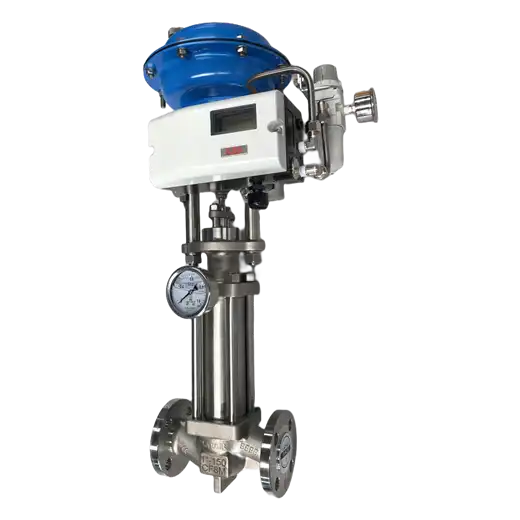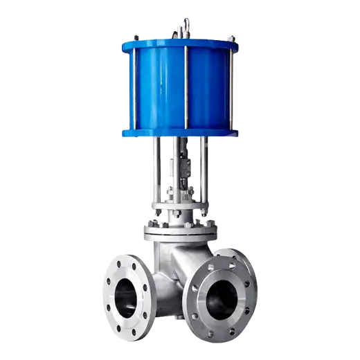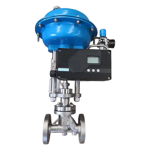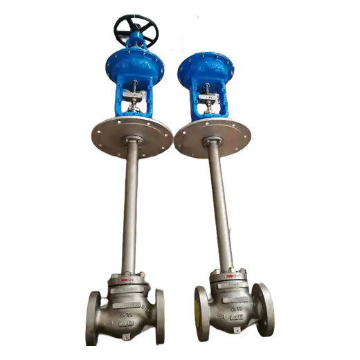
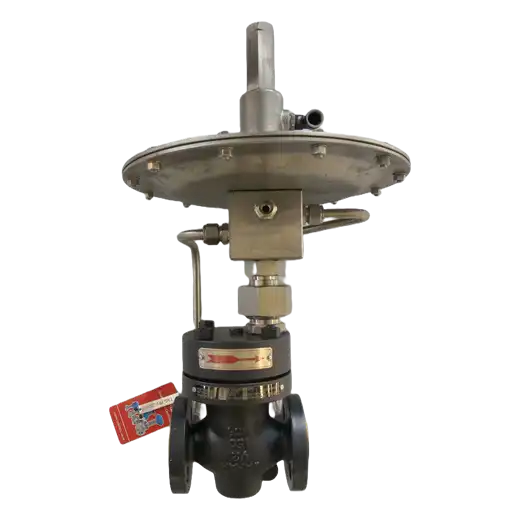
Self-Operated Micro Pressure Regulating Valve is a self-acting regulator that holds very low gas pressures stable using the medium's own energy, with no instrument air, no power supply and no positioner, across a set range typically 0.5 to 100 kPa for tank blanketing, gas holders and low-pressure gas distribution.
What We Need Before We Can Size It
A micro-pressure regulator is a small, inexpensive valve that is unusually easy to buy wrongly. The reason is that almost none of the parameters that determine whether it will work appear on a line list. Line size, class and material tell you what to bolt up; they say nothing about whether the valve will hold pressure. At a set point of a few kilopascals the available force is tiny, the controlled volume dominates the response, and the installation geometry — not the valve — decides whether the loop is stable or hunts. So before we can specify one properly, we need a short set of process data, and it is worth knowing what each item changes.
The first is the medium and its state: gas or liquid, composition, density, temperature, and whether the gas is clean, wet, corrosive or carries particulate. Density and temperature set the force available on the diaphragm, and cleanliness decides whether the valve needs a strainer upstream and whether the seat will survive. The second is the pressure profile, and this needs three numbers rather than one: the available upstream pressure, the required downstream set point, and the allowable variation around that set point. Micro-pressure regulators are sized on the differential across them and on the accuracy you can accept; a valve asked to hold 2 kPa from a source that itself varies between 5 and 50 kPa is a far harder problem than one holding 20 kPa from a steady 30 kPa source.
The third is flow: the maximum, minimum and normal rates, and whether the demand is steady or intermittent. Turndown decides the trim size and the number of valves; a wide ratio between a continuous bleed and an occasional large draw may need two regulators in parallel rather than one large valve working at the bottom of its range. The fourth is the controlled volume and its dynamics — the volume between the valve and the point where pressure must be held, and how quickly demand changes. A regulator feeding a large tank responds slowly and stably; the same regulator feeding a short length of pipe responds quickly and may oscillate. This is the parameter most often omitted from enquiries and most often responsible for a valve that "does not work" on site.
The fifth is the control arrangement, and it has two distinct forms that are not interchangeable. A downstream (pressure-reducing) type holds the pressure after the valve constant and is normally open, closing as downstream pressure rises — this is what a nitrogen blanketing supply uses. An upstream (back-pressure or relief) type holds the pressure before the valve constant and is normally closed, opening as upstream pressure rises — this is what protects a gas holder or vents a tank. Tank blanketing usually needs both, as a matched pair set a few hundred pascals apart, and neither does the other's job. Finally we need the installation constraints: available straight run downstream, where the sense line can be tapped, ambient conditions, and any hazardous-area classification. Send those and we will specify the valve, the spring range, the sense-line arrangement and the recommended installation — and we will tell you where a powered control valve with a positioner is the better choice, which it is whenever the set point has to be changed remotely or held to tighter accuracy than a spring can deliver.
Key Features
No External Power Source
Operates entirely on the energy of the controlled medium acting on a large-area diaphragm against a set spring. No instrument air, no electricity, no positioner and no signal loop — so it works on remote sites, in hazardous areas without certified instrumentation, during plant air failures, and anywhere a powered loop would be uneconomic to install.
Large-Area Diaphragm for Micro Pressures
Force equals pressure multiplied by area, and at a few kilopascals the available force is very small. The diaphragm effective area is therefore sized large enough to develop sufficient force to position the plug accurately, which is what distinguishes a true micro-pressure regulator from a standard self-acting valve simply re-sprung.
Adjustable Set Pressure by Spring Selection
The set point is adjusted by compressing the spring through an external adjusting screw, and the working range is fixed by the spring fitted. Multiple spring ranges are available for the same body, so one valve size covers different set points. Specify the required set point and the spring is supplied set and sealed where required.
Two Control Arrangements, Correctly Matched to the Duty
Downstream (pressure-reducing) type holds pressure after the valve and is normally open; upstream (back-pressure / relief) type holds pressure before the valve and is normally closed. Tank blanketing normally requires both as a matched pair. The two are not interchangeable, and specifying the wrong one is the most common error in this product class.
Balanced Trim for Insensitivity to Upstream Fluctuation
Balanced plug and balance-bellows arrangements prevent variation in the upstream supply pressure from being transmitted to the controlled pressure. Without balancing, a regulator supplied from a header whose pressure swings will pass those swings downstream regardless of how well it is set.
Soft Seat for Tight Shutoff at Low Differential
PTFE, reinforced PTFE, NBR, EPDM, FKM or silicone seats give bubble-tight closure at the very low seating forces available at micro pressures, preventing the continuous creep past a metal seat that wastes blanketing gas and allows the controlled pressure to drift upward.
Compact, Lightweight Construction
Brass, aluminium, carbon steel and stainless bodies in sizes from DN 15 to DN 100, with a compact diaphragm casing. The result is a valve that can be mounted directly on a tank nozzle or in a small skid without additional support — significant when the installation is on a tank roof or a remote wellsite.
Serviceable Without Removing the Valve
Diaphragm, spring, seat and plug are accessible from the topworks, so maintenance and spring-range changes are performed in the line. For dirty or wet media a replaceable upstream strainer protects the seat and the pilot passages and is the single most effective reliability measure available.
Typical Applications
| Duty | Typical Set Pressure Range | Valve Arrangement | Why Self-Operated Is Specified Here |
|---|---|---|---|
| Storage tank nitrogen blanketing | 0.5 - 5 kPa | Downstream (reducing) type on the nitrogen supply, plus upstream (relief) type on the vent, set a few hundred pascals apart | Tank roofs are remote from instrument air, the duty is continuous, and a powered loop is uneconomic per tank on a farm of many tanks. |
| Gas holder and biogas holder seal pressure | 1 - 10 kPa | Upstream (back-pressure) type, holding holder pressure as the bell rises and falls | Pressure varies continuously with holder position; a self-acting valve follows it without a controller, and the site is normally classified as a hazardous area. |
| Flare header and low-pressure vent system | 0.5 - 20 kPa | Upstream (relief) type maintaining minimum header back-pressure | The valve must operate during plant upset and instrument-air failure, exactly when a pneumatically actuated valve loses its power source. |
| Furnace, kiln and boiler draft control | 0.1 - 5 kPa (mm water column duty) | Downstream or upstream type depending on whether the draft is induced or forced | Draft pressures are far too low for a standard self-acting valve; a large-area diaphragm regulator is the conventional solution. |
| Low-pressure gas distribution and burner supply | 2 - 50 kPa | Downstream (reducing) type reducing from a header to a branch | Simple, maintenance-light pressure reduction where a positioner and signal loop would add cost and failure modes without benefit. |
| Fermentation, bioreactor and cleanroom gas supply | 1 - 30 kPa | Downstream (reducing) type on air, CO2 or nitrogen supply | Hygienic and washdown areas benefit from a valve with no electrical instrumentation to certify, and stainless construction is straightforward. |
| LNG and cryogenic tank boil-off management | 1 - 20 kPa | Upstream (relief) type on boil-off gas line, paired with a make-up regulator | Must remain functional without site utilities and at low temperature; extended bonnet and austenitic trim are specified accordingly. |
| Chemical and pharmaceutical reactor inerting | 0.5 - 15 kPa | Downstream (reducing) type on inert gas, with relief protection | Protects an inert atmosphere against air ingress and over-pressure without introducing an instrumented loop into a classified area. |
| Wastewater and digester gas pressure control | 1 - 10 kPa | Upstream (back-pressure) type on digester gas header | Wet, dirty and corrosive gas at remote locations; a self-acting valve with a strainer is more reliable and cheaper to maintain than an instrumented loop. |
| Seal gas and buffer gas supply | 2 - 40 kPa | Downstream (reducing) type maintaining a fixed offset above the sealed pressure | Requires a stable, continuously maintained differential rather than a set point that changes, which is exactly what a spring-set regulator delivers. |
What these duties share is a set of conditions that make a powered control loop the wrong tool: the pressure involved is a few kilopascals, the requirement is to hold one fixed value continuously, the location is remote or classified, and the valve must keep working when site utilities fail. That is precisely where a self-operated regulator earns its place — and equally, it defines where it should not be used. If the set point must be changed remotely or on a schedule, if the accuracy required is tighter than a spring and diaphragm can deliver, if the medium is liquid with a large differential, or if the flow turndown is wide and demand changes abruptly, a powered control valve with a positioner will outperform it and should be specified instead. We size from the process data set out above, supply the spring set to your declared set point, and issue an installation drawing showing the sense-line tap position and the required downstream straight run — because on a micro-pressure regulator, correct installation determines the outcome at least as much as correct selection.
Technical Specifications
Size, Pressure and Temperature
Valve Size: DN 15 - DN 100 (NPS 1/2 - NPS 4); larger sizes on request
Pressure Class: ASME Class 150 - Class 300; DIN PN 16 - PN 40 (body rating; the controlled pressure is far lower)
Set Pressure Range: 0.5 - 100 kPa typical (5 - 1000 mbar / 2 - 400 in w.c.), by spring range; sub-kilopascal and mm water column ranges available
Available Upstream Pressure: typically to 1000 kPa, dependent on spring range and valve type
Operating Temperature: -20 °C to +200 °C (-4 °F to +392 °F); extended bonnet and high-temperature diaphragm to +350 °C; low-temperature version to -196 °C
Valve Style: Straight (globe) pattern, Angle pattern
Control Arrangement and Accuracy
Valve Type: Downstream (pressure-reducing) type, normally open; Upstream (back-pressure / relief) type, normally closed
Set Pressure Adjustment: External adjusting screw compressing the set spring; multiple spring ranges per body size
Spring Ranges: Several overlapping ranges per size — specify the required set point and the applicable range is selected
Pressure Accuracy: typically ±5 - 10 % of set point, dependent on flow variation and installation; confirm per duty
Trim Balancing: Balanced plug with balance bellows, or unbalanced plug for the lowest set pressures
Sense Line Connection: Integrated internal sense passage, or external sense line tapped downstream (reducing type) or upstream (back-pressure type) per the installation drawing
Trim and Seating
Seat Type: Soft seat PTFE, Reinforced PTFE, NBR, EPDM, FKM, Silicone; metal-to-metal seat for high-temperature duty
Shutoff Capability: Bubble-tight with soft seat at micro-pressure seating loads; Class IV typical with metal seat per ANSI/FCI 70-2
Plug and Trim Material: 304, 316 / 316L, Brass, PTFE-faced; Stellite hard-faced for erosive duty
Flow Characteristic: Linear or Quick Opening — equal percentage is generally unsuitable at micro pressure and low turndown
Diaphragm: Large effective area elastomer or stainless diaphragm; materials NBR, EPDM, FKM, PTFE-faced, stainless for temperature and chemical resistance
Strainer: Replaceable upstream strainer recommended for wet, dirty or particulate-carrying media
Body and Material Options
Body Materials: Brass, Aluminium alloy, WCB carbon steel, CF8 / CF8M (304 / 316) stainless, LCB for low temperature, Duplex on request
Diaphragm Casing Materials: Carbon steel, 304 / 316 stainless, Aluminium
Spring Materials: Spring steel with corrosion-protective finish, 316 stainless for corrosive or offshore environments
Internal Components: 304 / 316 stainless, PTFE, Elastomer as applicable to the medium
Special Preparations: Oxygen-clean and degreased for oxygen service, Low-temperature impact tested, Food-grade elastomers for food and pharmaceutical contact
Connections and Mounting
End Connections: Flanged (ASME B16.5, DIN EN 1092-1), NPT / BSP threaded, Socket-weld, Sanitary clamp for hygienic duty
Sense Line Connection: 1/4" NPT or 3/8" NPT tapped boss for external sense line, or integral internal sensing
Mounting Orientation: Vertical with diaphragm casing above the body preferred; horizontal mounting acceptable subject to the installation drawing
Face-to-Face: EN 558 / ISO 5752, manufacturer's standard for compact sizes
Ambient Conditions: Suitable for outdoor and hazardous-area installation; no electrical certification required as the valve contains no instrumentation
Standards, Testing and Certification
Design Standards: EN 12516, ASME B16.34 where applicable, IEC 60534-3-2 / ISA 75.01 for face-to-face
Testing Standards: API 598, EN 12266-1, ISO 5208 shell and seat; set-pressure verification and accuracy test per unit
Certifications: CE / PED 2014/68/EU, ISO 9001, ATEX where the assembly includes electrical accessories, NACE MR0175 / ISO 15156 for sour service, FDA and EU 1935/2004 compliant elastomers for food and pharmaceutical duty
Documentation: Set-pressure test record, spring range identification, material certificates, installation drawing with sense-line tap position and required downstream straight run
Service Conditions and Media
Media: Nitrogen, Air, Natural gas, CO2, Biogas and digester gas, Boil-off gas, Flare and vent gas, Inert gases, Steam at reduced temperature, Clean liquids at low differential
Critical Service: Micro and very low pressure control, Tank blanketing, Hazardous area without instrument air, Fail-safe operation during utility loss, Remote and unattended sites, Continuous fixed-setpoint duty
Industries: Oil and Gas Storage and Terminals, Chemical and Petrochemical, Pharmaceuticals and Biotechnology, Food and Beverage, Water and Wastewater, Power, LNG, Metals and Heat Treatment, Agriculture and Biogas, Pulp and Paper
Commissioning and Installation Basis: Self-operated micro-pressure regulators fail far more often from installation than from selection. Four requirements govern performance and must be observed on site. First, the sense point must see the pressure you intend to control — the sense line taps downstream of the valve for a reducing type and upstream for a back-pressure type, never into a dead leg or an area of turbulence. Second, sufficient straight pipe run downstream allows the flow to settle before the sense point; a tap immediately after an elbow or a tee will make the valve hunt. Third, no isolation valve, restriction or check valve may be fitted between the valve and its sense point. Fourth, the controlled volume must be adequate: a regulator feeding a very small volume responds quickly and tends to oscillate, and a stabilising volume or a longer downstream run is the normal remedy. Spring range, set point and sense-line arrangement are supplied on the installation drawing, and set-pressure verification is recorded per unit.
When a Powered Control Valve Is the Better Choice: Where the set point must be changed remotely, on a schedule or in response to another variable; where accuracy tighter than a spring and diaphragm can deliver is required; where the medium is a liquid at substantial differential pressure; where flow turndown is wide and demand changes abruptly; and where the valve must be part of a safety instrumented function with defined proof testing. In these cases we will quote a control valve with a positioner and explain why.
Other Configurations: Consult our engineering team for set pressures outside the ranges above, sizes beyond DN 100, high-temperature and cryogenic versions, oxygen-clean construction, matched blanketing and relief valve pairs, pilot-operated versions for very low differential, or complete skid-mounted assemblies with strainers, isolation valves and pressure indication.
Frequently Asked Questions
What does "self-operated" mean, and how does it differ from a control valve?
A self-operated or self-acting regulator uses the energy of the controlled medium itself: process pressure acts on a diaphragm against a set spring, and the resulting force positions the plug directly. It needs no instrument air, no electricity, no positioner and no control signal. A conventional control valve has no intelligence of its own — a positioner receives a signal from a controller and drives an actuator. The self-acting regulator is therefore simpler, cheaper, works during utility failure and needs no hazardous-area certification, but it can only hold one fixed set point and its accuracy is limited by the spring and diaphragm.
What is the difference between the downstream and upstream types?
The downstream, or pressure-reducing, type holds the pressure after the valve constant; it is normally open and closes as downstream pressure rises. This is what a nitrogen blanketing supply uses. The upstream, or back-pressure / relief, type holds the pressure before the valve constant; it is normally closed and opens as upstream pressure rises, which is what protects a gas holder or vents a tank. They are not interchangeable. Tank blanketing normally requires both as a matched pair set a few hundred pascals apart, with the reducing valve admitting gas and the relief valve venting excess.
What accuracy can I expect, and what affects it?
Typically within plus or minus 5 to 10 percent of the set point for a standard design, and better on precision versions. Accuracy is degraded by wide variation in flow demand, by large fluctuation in the upstream supply pressure where the trim is not balanced, by an inadequately sized controlled volume, and above all by incorrect installation — a sense line tapped in a turbulent region or too close to a fitting will cause hunting regardless of the valve's quality. Tell us your allowable variation and we will confirm whether a self-acting regulator can meet it or whether a powered control valve is required.
Why does my self-operated regulator hunt or fail to hold pressure?
In our experience almost always for one of four installation reasons rather than a fault in the valve: the sense line is tapped too close to an elbow, tee or the valve outlet so it sees turbulence; an isolation valve, check valve or restriction has been fitted between the valve and the sense point; the downstream controlled volume is too small for the flow rate; or the spring range fitted does not match the required set point and the valve is working at the extreme of its adjustment. Check those four first. If all are correct, the next causes are a fouled or damaged seat, an upstream pressure that varies more than the trim can compensate for, or a flow turndown wider than one valve can handle.
Can this valve handle liquid service and high differential pressure?
Limited, and this is a genuine constraint rather than a matter of preference. A self-operated regulator generates its actuating force from the controlled pressure acting on the diaphragm, so at micro pressures the available force is small and the valve cannot seat against a large differential. It is designed for low-differential gas service and, to a lesser extent, low-differential liquid service. For liquid letdown at substantial differential pressure, or for any duty requiring high thrust, specify a powered control valve — and if cavitation or flashing is present, a staged trim rather than a single-restriction valve.
Resources
Data Sheets:
Manuals: IOM
Product Photos: