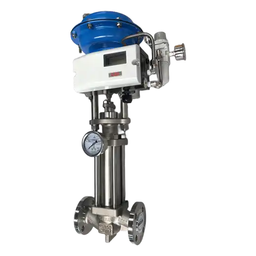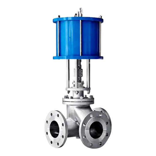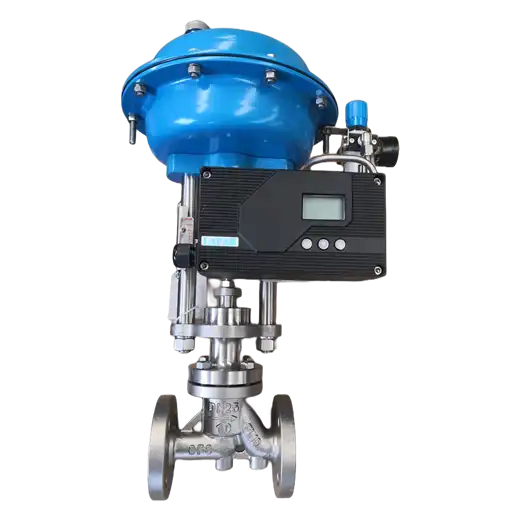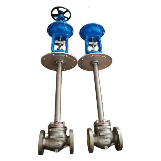
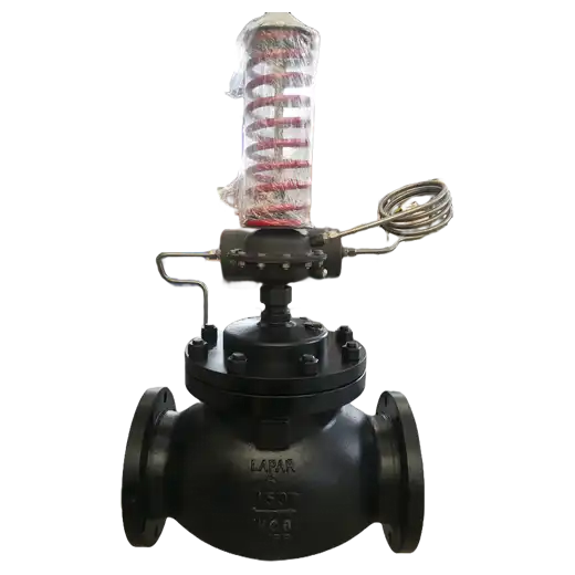
Self-operated pressure control valve fitted with a condensate chamber keeps the process steam pressure steady by taking its own energy from the line, and keeps that steam from destroying the actuator by putting a condensate barrier between the two.
Product Description
A self-operated pressure valve settles on its own setpoint without instrument air, external power or a controller, because the downstream pressure acts directly on a diaphragm or piston that balances against an adjustable spring. That simplicity is genuinely valuable on pressure-reducing duty: no air supply to route, no cable to pull, no loop to commission, and high reliability from an assembly with few parts. Its limit has historically been temperature. Above a certain fluid temperature, the elastomer diaphragm that makes the actuator work simply cannot survive contact with the medium.
The condensate chamber solves exactly that problem, and it is worth being precise about how. The chamber is an intermediate vessel mounted between the valve body and the actuator. Steam entering it condenses, forming a body of condensate that rests between the hot process and the actuator internals. The process pressure is transmitted hydraulically through that condensate column, so the actuator responds to the process correctly, while the diaphragm itself stays at a temperature set by the condensate rather than by live steam. It works because water is essentially incompressible and transmits pressure, but conducts only a fraction of the heat that the steam would. Without it, steam service at this temperature either eats diaphragms rapidly or forces you onto a pilot-operated or externally-actuated arrangement with considerably more cost and complexity.
There is an operating consequence worth knowing before installation: the chamber must contain its condensate charge to work. That means it has to be filled at commissioning, and it can lose that charge if the chamber is drained, if the trace freezes, or if the geometry permits condensate to be swept out by the process. A chamber without its water seal is no longer protecting anything, even though the valve appears to function. This is the most common field failure of this arrangement, and it is commissioning discipline rather than a design flaw — but it does mean this configuration belongs where someone will check it, not where nobody will look for a year.
How this differs from our other self-operated products: our general self-operated pressure control valve is intended for media already compatible with the actuator — gases, water, mild liquids at ordinary temperature. This version exists for the case where the medium is steam hot enough to damage a diaphragm. And unlike our pilot-operated control valve, it still contains no pilot stage and no external sensing line logic: it remains a direct-acting device whose entire input is the pressure it sees through the chamber.
Key Features
- No external power or instrument air: the valve takes its own motive energy from the process, so there is nothing to power, route or maintain beyond the valve itself.
- Condensate barrier protecting the actuator: the chamber transmits process pressure hydraulically while keeping the diaphragm clear of live steam temperature, extending actuator service life.
- Direct acting simplicity: a balanced spring against sensed downstream pressure, with no pilot stage, no controller and no position feedback loop to commission or tune.
- Adjustable setpoint: downstream pressure is set by means of the spring adjustment, with the setpoint range depending on the fitted spring — the range is a selection item, not a universal figure.
- Defined leak tightness: manufactured to the standard seat leakage classes, with achievable class depending on size and trim.
- Reduced ownership cost versus externally actuated alternatives: no air supply, no cabling, no control loop commissioning, and few moving parts to fail.
Typical Applications
- Steam pressure reducing stations — holding a stable reduced steam pressure downstream of the main header, where the medium would otherwise damage the actuator.
- Steam supply to process equipment — dedicated take-off serving dryers, presses, reactors and heat exchangers at a fixed reduced pressure.
- Boiler auxiliaries and tracing supply — feeding steam tracing networks and auxiliary consumers from a higher-pressure source.
- HVAC humidification and heating supply — localised pressure reduction on building steam distribution.
- Remote or unattended reducing duty — where there is no instrument air available and simplicity outweighs the need for remote setpoint control.
This arrangement is chosen when two conditions meet at once: the duty is genuinely simple enough that a self-acting regulator will hold the tolerance, and the medium is hot enough that it would otherwise destroy the actuator. Where both hold, nothing else in the catalogue is as economical. Where the setpoint has to change remotely, or the tolerance is tight enough to need tuning against loop lag, this is the wrong tool and an electropneumatic or pilot arrangement belongs there instead. Tell us the upstream and downstream pressures, the steam temperature and the setpoint range you need, and we will confirm the correct chamber arrangement and spring range — and tell you plainly if your conditions sit outside what this configuration should be asked to do.
Technical Specifications
| Valve Size | NPS 1/2 – NPS 12 / DN 15 – DN 300 |
|---|---|
| Pressure Class | ASME Class 150 to 600; DIN PN16 to PN100 |
| Operating Temperature | Up to +350 °C / +662 °F at the body |
| Body Style | Globe (Straight) |
| Process Connection | Flanged |
| Body Material | Carbon Steel, Stainless Steel, Alloy Steel |
| Trim | Contoured plug with proportional characteristic |
| Seat Leakage | Class IV per ANSI/FCI 70-2 |
| Setpoint Range | 0.01~2.0 MPa |
| Control Type | Self-Operated, Direct Acting — no external energy, no instrument air |
| Condensate Chamber | Fitted as standard; requires condensate charge at commissioning |
| Control Function | Pressure Reducing — downstream sensed after the valve |
| Actuator | Diaphragm or Piston, spring-opposed |
| Accessories | Sensing Line, Isolation Valve, Gauge, Strainer |
| Critical Service | Steam Pressure Reduction, Steam Supply Regulation, Pressure Reducing without Instrument Air |
| Media | Steam, Hot Water, Non-Corrosive Liquids and Gases |
| Industries | Power, Chemical & Petrochemical, HVAC & District Energy, Pulp & Paper, Food & Beverage |
Frequently Asked Questions
Why does this valve need a condensate chamber?
Because steam at working temperature will destroy the elastomer diaphragm that makes a self-acting actuator possible. The chamber sits between body and actuator, holds condensate, and transmits pressure hydraulically through that liquid column. Pressure passes accurately because water is effectively incompressible; heat largely does not. The result is a valve that senses real process pressure while keeping the diaphragm clear of live steam temperature.
Do I have to fill it with water before start-up?
Yes. The chamber must contain its condensate charge to function as a barrier. If it is empty, pressure still transmits, but the diaphragm is now in steam service for which it was not rated. The chamber should be charged at commissioning, and any subsequent draining, freezing or loss of the water seal removes the protection. Loss of the condensate charge is the most common field failure of this arrangement.
How is this different from a standard self-operated pressure valve?
The standard unit assumes the medium is already compatible with the actuator — clean water, gas or mild liquid at ordinary temperature. This version adds the chamber specifically so that steam can be handled without abandoning self-acting operation. If your medium is not hot enough to threaten a diaphragm, the simpler valve without the chamber is usually the better value.
Does it need instrument air or electricity?
No. Downstream pressure acting against an adjustable spring provides all the energy the valve needs. There is no air supply, no cabling and no controller. That is the principal reason for choosing this design, and also its principal limitation: the setpoint is adjusted locally at the valve rather than remotely.
What limits does the setpoint range have?
The achievable downstream pressure range is determined by which spring is fitted, not by a value common to all sizes. Provide your inlet pressure, required outlet pressure and flow range, and we will identify the correct spring rather than quote a generic range that may not cover your duty.
Resources
Data Sheets:
Manuals: IOM
Product Photos: