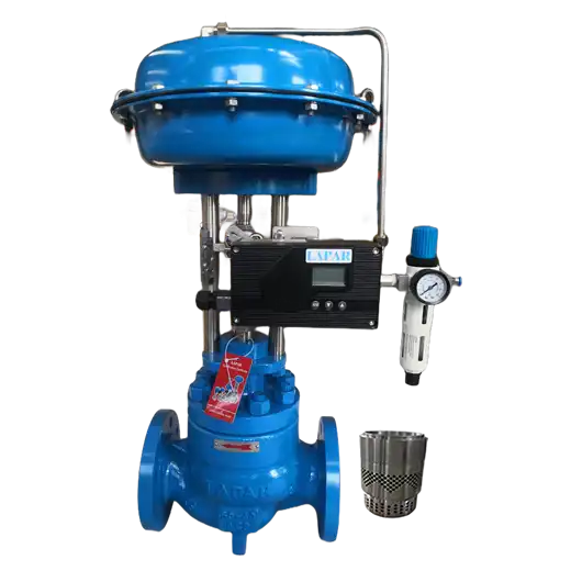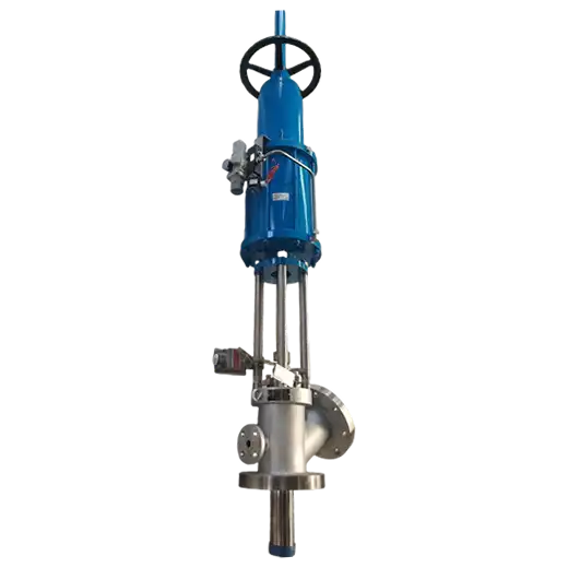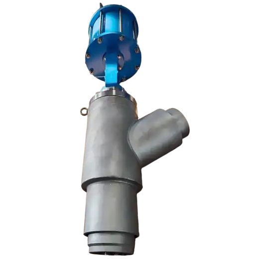
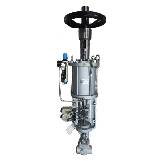
Power plant drain control valve modulates boiler blowdown and drain water — saturated liquid that partly flashes to vapour the moment it crosses the seat — and is built to survive that phase change continuously rather than occasionally.
Product Description
Saturated boiler water entering a drain line is close to its boiling point at line pressure. Reduce that pressure across a restriction and a fraction of the liquid instantly vaporises, because the fluid can no longer remain liquid at the lower pressure. The resulting two-phase mixture moves far faster than liquid alone and carries the energy that erodes conventional trim. In continuous blowdown service this happens every minute the plant runs, not once during a transient, which is why drain control valves fail in a pattern that looks mysterious until you understand flashing.
The remedy is to stop treating pressure reduction as a single event. Staged trim divides the total drop across a series of restrictions, so each stage handles a fraction of the fall and no single point sees the full differential. Because the fluid recovers to intermediate pressure between stages, later stages work at less severe conditions than a single restriction would face. Hardened trim materials add the second line of defence, resisting the erosion that remains even after staging. Together these are what turn drain valves from a planned-replacement item into something that survives between outages.
Two further points decide whether a specific installation works. First, flashing is not cavitation, and mixing them up leads to the wrong selection: cavitation involves bubble collapse because downstream pressure recovers above vapour pressure, whereas flashing persists because downstream pressure stays below it. Both damage trim, but they are predicted and mitigated differently, and only one of them is usually present in a given drain line. Second, sizing matters more here than on clean liquid service, because predicting two-phase behaviour through a restriction is not the same calculation as single-phase sizing. Supplying accurate upstream conditions and downstream pressure is what makes selection meaningful.
Where this valve sits relative to our other severe-service products: our power plant drain ball valve is pure isolation and must not be used to throttle — this valve is the one that modulates. And while our multi-stage anti-cavitation valve addresses high-pressure-drop liquid service across the plant generally, this model is specific to boiler drain and blowdown duty: saturated water, defined line sizes, and the operational pattern of a power plant.
Key Features
- Staged pressure reduction: the differential is taken across a series of restrictions so no single point carries the full drop, with interstage pressure recovery reducing downstream severity.
- Hardened trim materials: trim selected for resistance to the erosive two-phase flow that remains even after staging.
- Flashing-service geometry: internal passages arranged to handle greatly increased volumetric flow as vapour forms, rather than choking the flow path.
- Defined leakage classification: seat leakage stated per ANSI/FCI 70-2, so shutoff is a specified property rather than an assertion.
- Replaceable trim: wear components designed for changeout during planned outages without removing the body from the line.
- Power-plant actuation: accepts standard pneumatic or electric actuation with the accessories a blowdown loop expects.
Typical Applications
- Continuous boiler blowdown control — modulating the steady bleed that holds dissolved solids within limits, running continuously while the unit is online.
- Intermittent bottom blowdown — controlled discharge of accumulated sludge from the lower headers.
- Boiler drain during startup and shutdown — controlled draining with acceptable pressure management during warm-up and cool-down.
- Flash vessel and blowdown tank feed — throttling into a lower-pressure vessel where substantial flashing is expected.
- Heat recovery blowdown circuits — controlled discharge where heat is recovered before the stream reaches the blowdown vessel.
Drain and blowdown duty looks undemanding on paper — water, a moderate line size, a modest pressure. It is not, because the fluid changes phase while passing through the valve, and that single fact drives the entire design. If you are replacing drain valves more often than you should, look at whether the trim is staged, whether the material resists two-phase erosion, and whether the valve was sized for flashing rather than for clean liquid. Give us upstream pressure and temperature, downstream pressure, and required flow, and we will size it for the actual two-phase behaviour rather than for water.
Technical Specifications
| Valve Size | NPS 1/2 – NPS 6 / DN 15 – DN 150 |
|---|---|
| Pressure Class | ASME Class 600 to 1500 |
| Operating Temperature | Up to +350 °C / +662 °F |
| Body Style | Globe (Straight), Angle, Y-Pattern |
| Process Connection | Butt Weld, Flanged (RF / RTJ), Socket Weld |
| Body Material | Alloy Steel, Stainless Steel |
| Trim Type | Staged / Multi-Step Trim — drilled cage, stacked plate or labyrinth |
| Trim Material | Hardened Stainless Steel, Stellite |
| Stem Seal | Graphite Packing; bellows seal available |
| Seat Leakage | Class IV, Class V per ANSI/FCI 70-2 |
| Flow Characteristics | Linear, Equal Percentage, Custom |
| Actuator | Pneumatic Diaphragm, Piston, Electric |
| Critical Service | Boiler Blowdown, Continuous Blowdown, Flashing Water, High Differential Liquid, Drain Control |
| Certifications | ASME, PED |
| Media | Boiler Water, Blowdown Water, Condensate, Saturated Water |
| Industries | Power Generation, Thermal Power Plant, Industrial Boiler, Combined Heat and Power |
Frequently Asked Questions
Why do drain control valves wear out far faster than other valves on the same boiler?
Because the water flashes. Saturated boiler water partly vaporises as pressure falls across the seat, producing a high-velocity two-phase stream that erodes trim continuously. A valve selected and sized for single-phase liquid will not survive that duty even though the pressures on paper look unremarkable.
Is flashing the same as cavitation?
No. Cavitation occurs when pressure falls below the vapour pressure and then recovers above it, collapsing bubbles and damaging adjacent surfaces. Flashing persists because downstream pressure stays below vapour pressure, so vapour remains in the stream. Both are destructive but they are predicted and mitigated differently, and correct trim selection depends on identifying which one the duty actually produces.
Can I use a ball valve instead?
Not for throttling. Our power plant drain ball valve is a metal-seated isolation device and will lose its shutoff if held partly open in flashing service. Where a position must isolate, use the ball valve; where it must modulate, use this one.
How should this valve be sized?
For two-phase behaviour rather than clean liquid. That requires accurate upstream pressure and temperature, downstream pressure and required flow. Provide those values and the sizing reflects what the valve will actually see. Supplying only a line size and a nominal pressure almost guarantees a poor selection.
How often will the trim need replacing?
Service life depends on differential, cycle duty and water chemistry — no honest answer exists without those inputs. Staged reduction and hardened trim extend intervals substantially versus single-stage trim, but the valve should still be treated as a maintained component rather than a fit-and-forget one.